Page 1891 of 3371
EM-8Revision: August 2007
PREPARATION
2004 QX56
Valve guide reamer 1: Reaming valve guide hole
2: Reaming hole for oversize valve guide
Intake & Exhaust:
d
1 : 6.0 mm (0.236 in) dia.
d
2 : 10.175 - 10.196 mm (0.4006 - 0.4014 in)
dia.
Front oil seal drift Installing front oil seal
Rear oil seal drift Installing rear oil seal
(J-43897-18)
(J-43897-12)
Oxygen sensor thread cleanerReconditioning the exhaust system threads
before installing a new A/F sensor and heated
oxygen sensor (Use with anti-seize lubricant
shown below.)
a: J-43897-18 (18 mm dia.) for zirconia
heated oxygen sensor
b: J-43897-12 (12 mm dia.) for titania heat-
ed oxygen sensor
Anti-seize lubricant (Permatex 133AR
or equivalent meeting MIL specifica-
tion MIL-A-907)Lubricating A/F sensors and heated oxygen
sensor thread cleaning tool when recondition-
ing exhaust system threads (Kent-Moore No.)
Tool nameDescription
S-NT016
ZZA0012D
ZZA0025D
AEM488
AEM489
Page 1902 of 3371

EXHAUST MANIFOLD AND THREE WAY CATALYST
EM-19
C
D
E
F
G
H
I
J
K
L
MA
EM
Revision: August 20072004 QX56
EXHAUST MANIFOLD AND THREE WAY CATALYSTPFP:14004
Removal and InstallationEBS00ILG
REMOVAL
WA RN ING:
Perform the work when the exhaust and cooling system have cooled sufficiently.
1. Remove air duct and resonator assembly. Refer to EM-14, "
REMOVAL" .
2. Drain engine coolant from the radiator. Refer to MA-12, "
DRAINING ENGINE COOLANT" .
3. Remove engine undercover using power tool.
4. Remove the radiator and radiator hoses. Refer to CO-10, "
RADIATOR" .
5. Remove the drive belts. Refer to EM-12, "
Removal" .
6. Remove the air fuel ratio A/F sensors (right bank, left bank), using the following steps.
a. Remove engine room cover using power tool. Refer to EM-11, "
REMOVAL" .
b. Remove harness connector of each air fuel ratio A/F sensors, and harness from bracket and middle
clamp.
1. Air fuel ratio (A/F) sensor 1 (bank 2) 2. Exhaust manifold cover (bank 2) 3. Exhaust manifold (bank 2)
4. Gaskets 5. Exhaust manifold (left bank 1) 6. Exhaust manifold cover (bank 1)
7. Air fuel ratio (A/F) sensor 1 (bank 1)
WBIA0466E
Page 1903 of 3371

EM-20Revision: August 2007
EXHAUST MANIFOLD AND THREE WAY CATALYST
2004 QX56
c. Remove the air fuel ratio A/F sensors from both left and right
exhaust manifolds using Tool.
CAUTION:
�Be careful not to damage the air fuel ratio A/F sensors
�Discard any air fuel ratio A/F sensor which has been
dropped from a height of more than 0.5m (19.7 in) onto a
hard surface such as a concrete floor. Replace it with a
new one.
7. Remove the front cross bar.
8. Remove the exhaust manifold (left bank) using the following
steps.
a. Remove the exhaust front tube using power tool. Refer to EX-3,
"Removal and Installation" .
b. Remove the exhaust manifold cover.
c. Loosen the nuts in reverse order shown using power tool.
d. Remove the exhaust studs from positions 2, 4, 6, 8 and remove
the left exhaust manifold.
9. Remove the exhaust manifold (right bank) using the following
steps.
a. Remove the exhaust front tube using power tool. Refer to EX-3,
"Removal and Installation" .
b. Remove the oil level gauge guide. Refer to EM-22, "
OIL PAN
AND OIL STRAINER" .
c. Remove the exhaust manifold cover.
d. Loosen the nuts in reverse order shown using power tool.
e. Remove the exhaust studs from positions 2, 4, 6, 8 and remove the right exhaust manifold.
INSPECTION AFTER REMOVAL
Surface Distortion
�Use a reliable straightedge and feeler gauge to check the flat-
ness of each exhaust manifold flange surface.
�If flatness exceeds the limit, replace the exhaust manifold.
INSTALLATION
Installation is in the reverse order of removal.
�Install a new exhaust manifold gasket with the top of the triangu-
lar up mark on it facing up and its coated face (gray side) toward
the exhaust manifold side.Tool number : — (J-44626)
WBIA0630E
KBIA2464E
Flatness limit : 0.3 mm (0.012 in)
KBIA2504E
KBIA2553E
Page 1904 of 3371
EXHAUST MANIFOLD AND THREE WAY CATALYST
EM-21
C
D
E
F
G
H
I
J
K
L
MA
EM
Revision: August 20072004 QX56
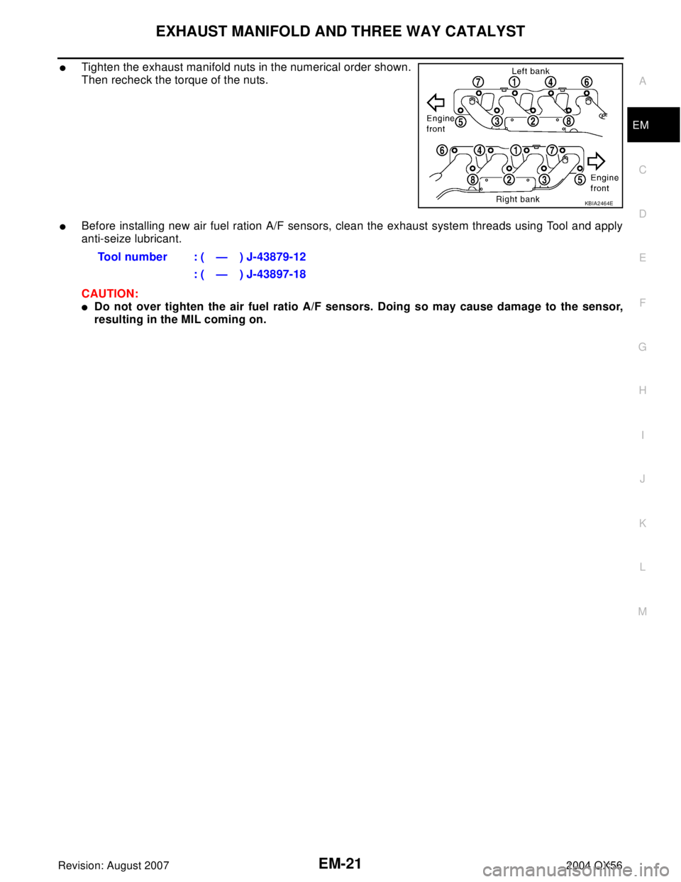
�Tighten the exhaust manifold nuts in the numerical order shown.
Then recheck the torque of the nuts.
�Before installing new air fuel ration A/F sensors, clean the exhaust system threads using Tool and apply
anti-seize lubricant.
CAUTION:
�Do not over tighten the air fuel ratio A/F sensors. Doing so may cause damage to the sensor,
resulting in the MIL coming on.
KBIA2464E
Tool number : ( — ) J-43879-12
: ( — ) J-43897-18
Page 1926 of 3371
CAMSHAFT
EM-43
C
D
E
F
G
H
I
J
K
L
MA
EM
Revision: August 20072004 QX56
CAMSHAFTPFP:13001
Removal and InstallationEBS00ILN
* Refer to GI-45, "Recommended Chemical Products and Sealants" .
REMOVAL
1. Remove rocker cover (right bank) and (left bank). Refer to EM-33, "ROCKER COVER" .
2. Obtain compression TDC of No. 1 cylinder as follows:
a. Turn crankshaft pulley clockwise to align the TDC identification
notch (without paint mark) with timing indicator on front cover.
1. Cylinder head (right bank) 2. Camshaft bracket (No. 2, 3, 4, 5) 3. Valve lifter
4. Camshaft bracket (No. 1) 5. Seal washer 6. Camshaft (right bank EXH)
7. Camshaft (right bank INT) 8. Camshaft (left bank INT) 9. Camshaft (left bank EXH)
10. Camshaft sprocket (right bank EXH) 11. Camshaft sprocket (right bank INT) 12. Camshaft sprocket (left bank INT)
13. Camshaft sprocket (left bank EXH) 14. Camshaft position sensor (PHASE) 15. O-ring
16. Cylinder head (left bank)
WBIA0469E
KBIA2476E
Page 1943 of 3371

EM-60Revision: August 2007
CYLINDER HEAD
2004 QX56
Removal and InstallationEBS00ILT
REMOVAL
1. Remove engine assembly from vehicle. Refer to EM-70, "REMOVAL" .
2. Remove the following components and related parts:
�Auto tensioner of drive belts and idler pulley. Refer to EM-12, "DRIVE BELTS" .
�Thermostat housing and hose. Refer to CO-17, "Removal of Thermostat Housing, Water Outlet and
Heater Pipe" .
�Oil pan and oil strainer. Refer to EM-22, "OIL PAN AND OIL STRAINER" .
�Fuel tube and fuel injector assembly. Refer to EM-29, "FUEL INJECTOR AND FUEL TUBE" .
�Intake manifold. Refer to EM-15, "INTAKE MANIFOLD" .
�Ignition coil. Refer to EM-26, "IGNITION COIL" .
�Rocker cover. Refer to EM-33, "ROCKER COVER" .
3. Remove crankshaft pulley, front cover, oil pump, and timing chain. Refer to EM-35, "
TIMING CHAIN" .
4. Remove camshaft sprockets and camshafts. Refer to EM-43, "
CAMSHAFT" .
5. Remove cylinder head bolts in reverse order shown.
1. Harness bracket 2. Engine coolant temperature sensor 3. Washer
4. Cylinder head gasket (left bank) 5. Cylinder head (right bank) 6. Cylinder head bolt
7. Cylinder head gasket (right bank) 8. Cylinder head (left bank)
KBIA2528E
PBIC0068E
Page 1957 of 3371

EM-74Revision: August 2007
CYLINDER BLOCK
2004 QX56
* Refer to GI-45, "Recommended Chemical Products and Sealants" .
DISASSEMBLY
1. Remove engine assembly. Refer to EM-70, "REMOVAL" .
2. Remove the drive plate.
�Hold the crankshaft pulley bolt to lock the crankshaft and remove the drive plate bolts.
�Loosen bolts diagonally.
CAUTION:
�Be careful not to damage drive plate. Especially avoid
deforming and damaging of signal plate teeth (circum-
ference position).
�Place the drive plate with signal plate surface facing
other than downward.
�Keep magnetic materials away from signal plate.
3. Lift the engine with hoist to install it onto engine stand. Refer to EM-70, "
REMOVAL" .
CAUTION:
�Use an engine stand that has a load capacity [approximately 240kg (529 lb) or more] large
enough for supporting the engine weight.
�Before removing the hanging chains, make sure the engine stand is stable and there is no risk
of overturning.
�If the load capacity of the stand is not adequate, remove the following parts beforehand to reduce the
potential risk of overturning the stand.
–Remove fuel tube and fuel injector assembly. Refer to EM-29, "REMOVAL" .
–Remove intake manifold. Refer to EM-15, "REMOVAL" .
–Remove exhaust manifold. Refer to EM-19, "REMOVAL" .
–Remove A/C compressor fitting bolts and brackets. Refer to ATC-166, "REMOVAL" .
–Remove ignition coil. Refer to EM-26, "REMOVAL" .
–Remove rocker cover. Refer to EM-33, "REMOVAL" .
–Other removable brackets.
4. Drain engine oil. Refer to MA-16, "
Changing Engine Oil" .
1. Knock sensor sub-harness 2. Knock sensor 3. Cylinder block
4. Main bearing 5. Top ring 6. Second ring
7. Oil ring 8. Crankshaft key 9. Piston
10. Connecting rod 11. Snap ring 12. Piston pin
13. Connecting rod bearing 14. Connecting rod bearing cap 15. Main bearing cap
16. Thrust bearing 17. Main bearing 18. Crankshaft
19. Pilot converter 20. Thrust bearing 21. Side bolt
22. Drive plate 23. Reinforcement plate 24. Rear oil seal retainer
25. Rear oil seal 26. Transmission 27. O-ring
28. Crankshaft position sensor (POS) 29. Gasket 30. Cylinder block heater
31. Connector cap
KBIA2491E
Page 1958 of 3371

CYLINDER BLOCK
EM-75
C
D
E
F
G
H
I
J
K
L
MA
EM
Revision: August 20072004 QX56
5. Drain engine coolant by removing cylinder block drain plug “A”,
“B”, “C” and “D” as shown.
6. Remove the following components and associated parts (The parts listed in step 3 are not included here.)
�Oil pan and oil strainer. Refer to EM-22, "REMOVAL" .
�Crankshaft pulley, front cover and timing chain. Refer to EM-36, "REMOVAL" .
�Camshaft. Refer to EM-43, "REMOVAL" .
�Cylinder head. Refer to EM-60, "REMOVAL" .
7. Remove knock sensor.
CAUTION:
Carefully handle the sensor, avoiding shocks.
8. Remove the piston and connecting rod assembly as follows.
�Before removing the piston and connecting rod assembly, check the connecting rod side clearance.
Refer to EM-89, "
CONNECTING ROD SIDE CLEARANCE" .
a. Position the crankshaft pin corresponding to the connecting rod to be removed onto the bottom dead cen-
ter.
b. Remove the connecting rod cap.
c. Push the piston and connecting rod assembly out to the cylinder
head side using suitable tool.
9. Remove the connecting rod bearings.
CAUTION:
When removing them, note the installation position. Keep them in the correct order.
10. Remove the piston rings from the piston using suitable tool.
CAUTION:
�When removing the piston rings, be careful not to dam-
age the piston.
�Be careful not to damage piston rings by expanding them
excessively.
�Before removing the piston rings, check the piston ring side
clearance. Refer to EM-90, "
PISTON RING SIDE CLEARANCE"
.
WBIA0419E
PBIC0086E
PBIC0087E
 dia.
d
2 : 10.175 -")