Page 2051 of 3371

FL-6Revision: August 2007
FUEL LEVEL SENSOR UNIT, FUEL FILTER AND FUEL PUMP ASSEMBLY
2004 QX56
d. Disconnect the fuel filler hose from the fuel filler pipe.
e. Insert a suitable hose into the fuel tank through the fuel filler hose to drain the fuel from the fuel tank.
�As a guide, the fuel level reaches the fuel gauge position as shown, or less, when approximately 14
liters (3 3/4 US gal, 3 1/8 Imp gal) of fuel are drained from the fuel tank.
3. Release the fuel pressure from the fuel lines. Refer to EC-46, "
FUEL PRESSURE RELEASE" .
4. Remove the second row LH rear seat and the third row rear seat. Refer to SE-103, "
REAR SEAT" .
5. Remove the second and third row rear seat belt buckles mounted on the floor. Refer to SB-3, "
SEAT
BELTS" .
6. Remove the LH center pillar trim, the LH rear trim panel, and the LH rear side door kick plate and weather
stripping. Refer to EI-34, "
BODY SIDE TRIM" .
7. Remove the second row rear center console and base, if equipped. Refer to EI-36, "
FLOOR TRIM" .
8. Reposition the floor carpet out of the way to access the inspection hole cover, located under the center LH
rear seat.
9. Remove the inspection hole cover by turning the retainers 90°
degrees clockwise.
�Remove the O-ring.
10. Disconnect the fuel level sensor, fuel filter, and fuel pump
assembly electrical connector, the EVAP hose, and the fuel feed
hose.
LBIA0386E
LBIA0382E
LBIA0383E
Page 2052 of 3371

FUEL LEVEL SENSOR UNIT, FUEL FILTER AND FUEL PUMP ASSEMBLY
FL-7
C
D
E
F
G
H
I
J
K
L
MA
FL
Revision: August 20072004 QX56
Disconnect the quick connector as follows:
�Hold the sides of the connector, push in tabs and pull out the
tube.
�If the connector and the tube are stuck together, push and pull
several times until they start to move. Then disconnect them
by pulling.
CAUTION:
�The quick connector can be disconnected when the tabs
are completely depressed. Do not twist the quick connec-
tor more than necessary.
�Do not use any tools to disconnect the quick connector.
�Keep the resin tube away from heat. Be especially careful
when welding near the tube.
�Prevent any acid liquids such as battery electrolyte, from
getting on the resin tube.
�Do not bend or twist the resin tube during connection.
�Do not remove the remaining retainer on the hard tube (or
the equivalent) except when the resin tube or the retainer
is replaced.
�When the resin tube or hard tube, or the equivalent, is
replaced, also replace the retainer with a new one (white
colored retainer).
�To keep the quick connector clean and to avoid damage
and contamination from foreign materials, cover the
quick connector with plastic bags or suitable material as
shown.
SF E5 62 A
PBIC1268E
PBIC0163E
Page 2053 of 3371

FL-8Revision: August 2007
FUEL LEVEL SENSOR UNIT, FUEL FILTER AND FUEL PUMP ASSEMBLY
2004 QX56
11. Remove the lock ring using Tool.
12. Remove the fuel level sensor, fuel filter, and fuel pump assem-
bly.
CAUTION:
�Do not bend the float arm during removal.
�Avoid impacts such as dropping when handling the com-
ponents.
INSTALLATION
Installation is in the reverse order of removal.
�Connect the quick connector as follows:
–Check the connection for any damage or foreign materials.
–Align the connector with the pipe, then insert the connector straight into the pipe until a click is heard.
–After connecting the quick connector, make sure that the con-
nection is secure by checking as follows:
–Pull the tube and the connector to make sure they are securely
connected.
–Visually inspect the connector to make sure the two retainer tabs
are securely connected.
INSPECTION AFTER INSTALLATION
1. Turn the ignition switch ON but do not start engine, then check the fuel pipes and hose connections for
leaks while applying fuel pressure to the system.
2. Start the engine and rev it above idle speed, then check that there are no fuel leaks at any of the fuel pipe
and hose connections.Tool number : — (J-46536)
LBIA0389E
PBIC1653E
Page 2054 of 3371
FUEL TANK
FL-9
C
D
E
F
G
H
I
J
K
L
MA
FL
Revision: August 20072004 QX56
FUEL TANKPFP:17202
Removal and InstallationEBS00IKQ
1. Inspection hole cover 2. Inspection hole cover O-ring 3. Lock ring
4. Fuel level sensor, fuel filter, and fuel
pump assembly5. Fuel tank 6. Fuel tank protector
7. Fuel tank protector clips 8. Fuel tank straps 9. Fuel level sensor, fuel filter, and fuel
pump assembly O-ring
WBIA0443E
Page 2056 of 3371
FUEL TANK
FL-11
C
D
E
F
G
H
I
J
K
L
MA
FL
Revision: August 20072004 QX56
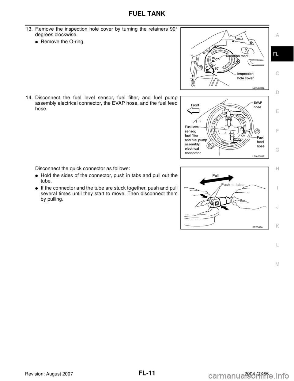
13. Remove the inspection hole cover by turning the retainers 90°
degrees clockwise.
�Remove the O-ring.
14. Disconnect the fuel level sensor, fuel filter, and fuel pump
assembly electrical connector, the EVAP hose, and the fuel feed
hose.
Disconnect the quick connector as follows:
�Hold the sides of the connector, push in tabs and pull out the
tube.
�If the connector and the tube are stuck together, push and pull
several times until they start to move. Then disconnect them
by pulling.
LBIA0382E
LBIA0383E
SF E5 62 A
Page 2058 of 3371

FUEL TANK
FL-13
C
D
E
F
G
H
I
J
K
L
MA
FL
Revision: August 20072004 QX56
19. Remove the fuel tank strap bolts while supporting the fuel tank
with a suitable lift jack.
20. Disconnect the EVAP hose from the molded clip in the top of the fuel tank while lowering the fuel tank.
21. Lower the fuel tank using a suitable lift jack and remove it.
22. If necessary, remove the lock ring using Tool.
23. If necessary, remove the fuel level sensor, fuel filter, and fuel
pump assembly.
CAUTION:
�Do not bend the float arm during removal.
�Avoid impacts such as dropping when handling the com-
ponents.
INSTALLATION
Installation is in the reverse order of removal.
�Connect the quick connector as follows:
–Check the connection for any damage or foreign materials.
–Align the connector with the pipe, then insert the connector straight into the pipe until a click is heard.
–After connecting the quick connector, make sure that the con-
nection is secure by checking as follows:
–Pull the tube and the connector to make sure they are securely
connected.
–Visually inspect the connector to make sure the two retainer tabs
are securely connected.
INSPECTION AFTER INSTALLATION
1. Turn the ignition switch ON but do not start engine, then check the fuel pipe and hose connections for
leaks while applying fuel pressure.
2. Start the engine and rev it above idle, then check that there are no fuel leaks at any of the fuel pipe and
hose connections.
LBIA0387E
Tool number : — (J-46536)
LBIA0389E
PBIC1653E
Page 2066 of 3371

ON-VEHICLE SERVICE
FSU-7
C
D
F
G
H
I
J
K
L
MA
B
FSU
Revision: August 20072004 QX56
�Check with the manufacturer of your specific alignment machine for their recommended Service/Cali-
bration Schedule.
THE ALIGNMENT PROCESS
IMPORTANT: Use only the alignment specifications listed in this Service Manual. Refer to FSU-21,
"Wheelarch Height (Unladen*1 )" .
1. When displaying the alignment settings, many alignment machines use “indicators”: (Green/red, plus or
minus, Go/No Go). Do NOT use these indicators.
�The alignment specifications programmed into your alignment machine that operate these indicators
may not be correct.
�This may result in an ERROR.
2. Some newer alignment machines are equipped with an optional “Rolling Compensation” method to “com-
pensate” the sensors (alignment targets or head units). Do NOT use this “Rolling Compensation”
method.
�Use the “Jacking Compensation” method. After installing the alignment targets or head units, raise the
vehicle and rotate the wheels 1/2 turn both ways.
�See Instructions in the alignment machine you are using for more information.
CAMBER AND CASTER
1. Measure camber and caster of both the right and left wheels
with a suitable alignment gauge and adjust as necessary to
specification.
2. If outside of the specified value, adjust camber and caster using
the adjusting bolts in the front lower link.
CAUTION:
After adjusting the camber then check the toe-in.
NOTE:
Camber changes about 3' (0.11°) with each graduation of one
adjusting bolt. Refer to table below for examples of lower link
adjusting bolt effect on camber and caster.
3. Tighten the adjusting bolt nuts to specification. Refer to FSU-5, "
Components" . Camber : Refer to FSU-20, "
Wheel Alignment
(Unladen*1 )" .
SRA0 96 A
LEIA0092E
Rear adjusting
bolt1 In 1 Out 1 In 1 Out 0 0 1 In 1 Out
Front adjusting
bolt1 Out 1 In 1 In 1 Out 1 In 1 Out 0 0
Camber
Degree minute
(Decimal degree)0 (0) 0 (0) 7' (0.11°)-7' (-0.11°)3' (0.11°) -3' (-0.11°)3' (0.11°) -3' (-0.11°)
Caster
Degree minute
(Decimal degree)-14' (-0.11°) 14' (0.11°) 0 (0) 0 (0) 7' (0.11°) -7' (-0.11°)-7' (-0.11°)7' (0.11°)
Page 2076 of 3371
 of each comp")
KNUCKLE
FSU-17
C
D
F
G
H
I
J
K
L
MA
B
FSU
Revision: August 20072004 QX56
KNUCKLEPFP:40014
On-Vehicle Inspection and ServiceEES0010R
Make sure the mounting conditions (looseness, backlash) of each component and component status (wear,
damage) are within specifications. Refer to FSU-21, "
Ball Joint" .
Removal and InstallationEES0010S
REMOVAL
1. Remove wheel and tire from vehicle using power tool.
2. Without disconnecting the hydraulic lines, remove brake caliper using power tool. Reposition it aside with
wire. Refer to BR-22, "
Removal and Installation of Brake Caliper and Disc Rotor" .
CAUTION:
It is not necessary to remove bolts on torque member and brake hose except for disassembly or
replacement of caliper assembly. In this case, hang cylinder body with a wire so that the brake
hose in not under tension.
NOTE:
Avoid depressing brake pedal while brake caliper is removed.
3. Put alignment marks on disc rotor and wheel hub and bearing
assembly, then remove disc rotor.
4. Remove ABS sensor from steering knuckle. Refer to BRC-64, "
Removal and Installation" .
CAUTION:
Do not pull on ABS sensor harness.
5. Remove cotter pin, then remove lock nut from drive shaft using power tool.
6. Remove steering outer socket cotter pin at steering knuckle, then loosen mounting nut using power tool.
1. Disc rotor 2. Wheel hub and bearing assembly 3. Wheel stud
4. Splash guard 5. Steering knuckle
WDIA0043E
WDIA0044E