Page 1655 of 3371

EC-464Revision: August 2007
DTC P1276, P1286 A/F SENSOR 1
2004 QX56
If the indication is constantly approx. 1.5V and does not fluctuates, go to EC-469, "Diagnostic Procedure"
.
If the indication fluctuates around 1.5V, go to next step.
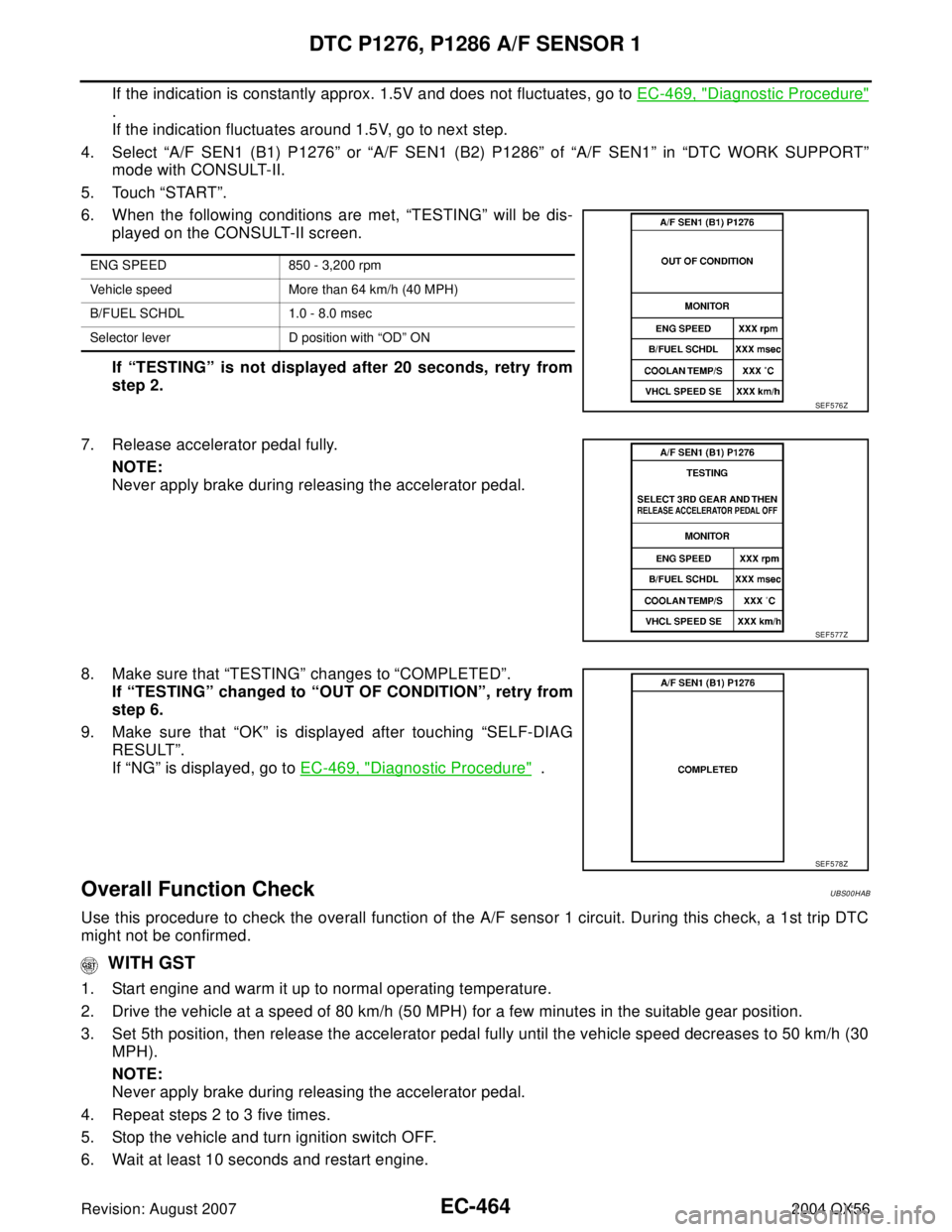
4. Select “A/F SEN1 (B1) P1276” or “A/F SEN1 (B2) P1286” of “A/F SEN1” in “DTC WORK SUPPORT”
mode with CONSULT-II.
5. Touch “START”.
6. When the following conditions are met, “TESTING” will be dis-
played on the CONSULT-II screen.
If “TESTING” is not displayed after 20 seconds, retry from
step 2.
7. Release accelerator pedal fully.
NOTE:
Never apply brake during releasing the accelerator pedal.
8. Make sure that “TESTING” changes to “COMPLETED”.
If “TESTING” changed to “OUT OF CONDITION”, retry from
step 6.
9. Make sure that “OK” is displayed after touching “SELF-DIAG
RESULT”.
If “NG” is displayed, go to EC-469, "
Diagnostic Procedure" .
Overall Function CheckUBS00HAB
Use this procedure to check the overall function of the A/F sensor 1 circuit. During this check, a 1st trip DTC
might not be confirmed.
WITH GST
1. Start engine and warm it up to normal operating temperature.
2. Drive the vehicle at a speed of 80 km/h (50 MPH) for a few minutes in the suitable gear position.
3. Set 5th position, then release the accelerator pedal fully until the vehicle speed decreases to 50 km/h (30
MPH).
NOTE:
Never apply brake during releasing the accelerator pedal.
4. Repeat steps 2 to 3 five times.
5. Stop the vehicle and turn ignition switch OFF.
6. Wait at least 10 seconds and restart engine.
ENG SPEED 850 - 3,200 rpm
Vehicle speed More than 64 km/h (40 MPH)
B/FUEL SCHDL 1.0 - 8.0 msec
Selector lever D position with “OD” ON
SEF 5 76 Z
SEF 5 77 Z
SEF 5 78 Z
Page 1656 of 3371
DTC P1276, P1286 A/F SENSOR 1
EC-465
C
D
E
F
G
H
I
J
K
L
MA
EC
Revision: August 20072004 QX56
7. Repeat steps 2 to 3 five times.
8. Stop the vehicle and connect GST to the vehicle.
9. Make sure that no DTC is displayed.
If the DTC is displayed, go to EC-469, "
Diagnostic Procedure" .
Page 1657 of 3371
EC-466Revision: August 2007
DTC P1276, P1286 A/F SENSOR 1
2004 QX56
Wiring DiagramUBS00HAC
BANK 1
BBWA1369E
Page 1658 of 3371
DTC P1276, P1286 A/F SENSOR 1
EC-467
C
D
E
F
G
H
I
J
K
L
MA
EC
Revision: August 20072004 QX56
Specification data are reference values and are measured between each terminal and ground.
CAUTION:
Do not use ECM ground terminals when measuring input/output voltage. Doing so may result in dam-
age to the ECM's transistor. Use a ground other than ECM terminals, such as the ground.
TER-
MINAL
NO.WIRE
COLORITEM CONDITION DATA (DC Voltage)
16 BR/R
A/F sensor 1 (Bank 1)[Engine is running]
�Warm-up condition
�Idle speedApproximately 3.1V
35 BR/GApproximately 2.6V
56 LG/BApproximately 2.3V
75 P/BApproximately 2.3V
Page 1659 of 3371
EC-468Revision: August 2007
DTC P1276, P1286 A/F SENSOR 1
2004 QX56
BANK 2
BBWA0919E
Page 1660 of 3371
DTC P1276, P1286 A/F SENSOR 1
EC-469
C
D
E
F
G
H
I
J
K
L
MA
EC
Revision: August 20072004 QX56
Specification data are reference values and are measured between each terminal and ground.
CAUTION:
Do not use ECM ground terminals when measuring input/output voltage. Doing so may result in dam-
age to the ECM's transistor. Use a ground other than ECM terminals, such as the ground.
Diagnostic ProcedureUBS00HAD
1. CHECK GROUND CONNECTIONS
1. Turn ignition switch OFF.
2. Loosen and retighten three ground screws on the body.
Refer to EC-133, "
Ground Inspection" .
OK or NG
OK >> GO TO 2.
NG >> Repair or replace ground connections.
TER-
MINAL
NO.WIRE
COLORITEM CONDITION DATA (DC Voltage)
57 L/P
A/F sensor 1 (Bank 2)[Engine is running]
�Warm-up condition
�Idle speedApproximately 2.6V
58 GR/GApproximately 2.3V
76 G/LApproximately 3.1V
77 BR/BApproximately 2.3V
BBIA0354E
Page 1661 of 3371
EC-470Revision: August 2007
DTC P1276, P1286 A/F SENSOR 1
2004 QX56
2. CHECK AIR FUEL RATIO (A/F) SENSOR 1 POWER SUPPLY CIRCUIT
1. Disconnect A/F sensor 1 harness connector.
2. Turn ignition switch ON.
3. Check voltage between A/F sensor 1 terminal 3 and ground with
CONSULT-II or tester.
OK or NG
OK >> GO TO 4.
NG >> GO TO 3.
3. DETECT MALFUNCTIONING PART
Check the following.
�Harness connectors E5, F14
�IPDM E/R harness connector E119
�10A fuse
�Harness for open or short between A/F sensor 1 and fuse
>> Repair or replace harness or connectors. Voltage: Battery voltage
BBIA0376E
PBIB1683E
Page 1662 of 3371

DTC P1276, P1286 A/F SENSOR 1
EC-471
C
D
E
F
G
H
I
J
K
L
MA
EC
Revision: August 20072004 QX56
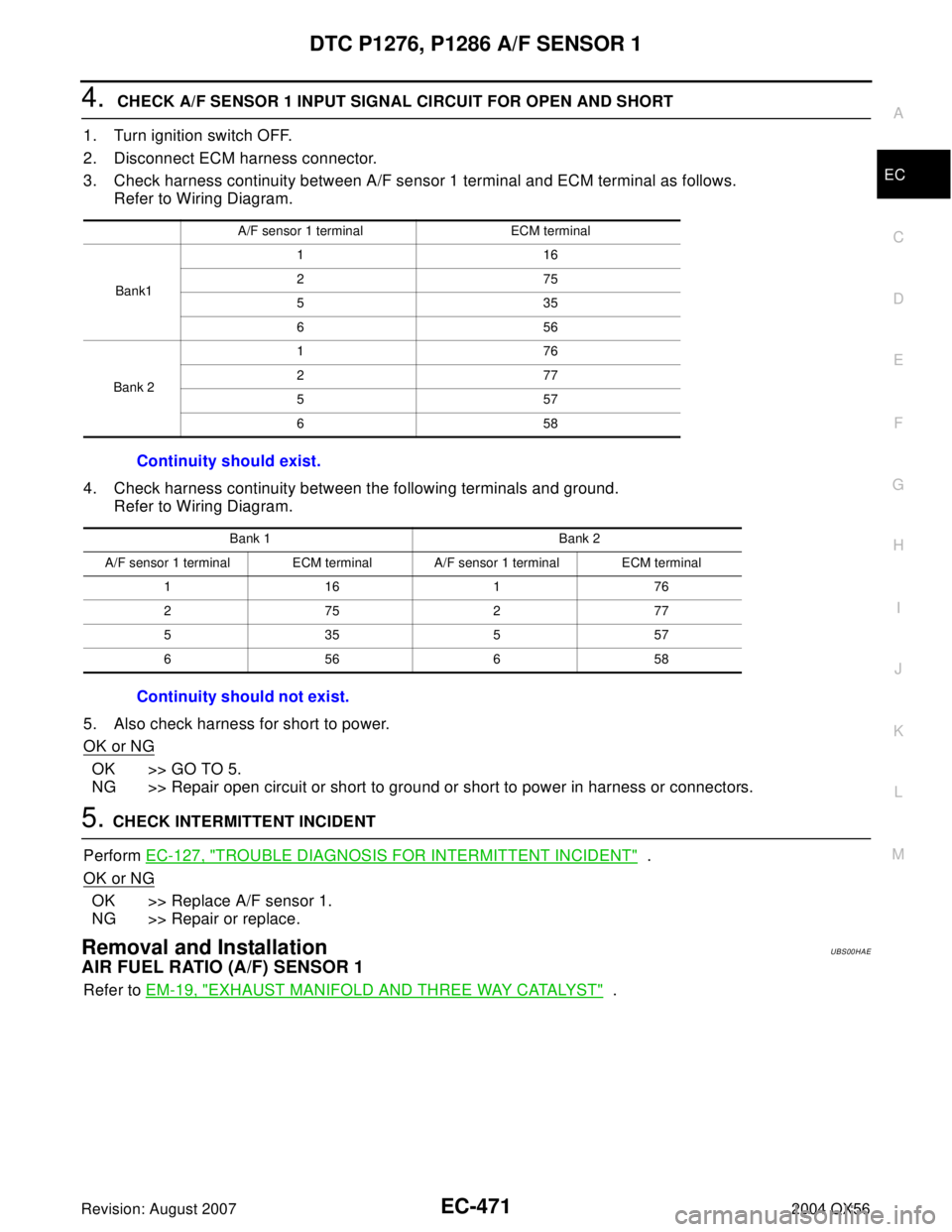
4. CHECK A/F SENSOR 1 INPUT SIGNAL CIRCUIT FOR OPEN AND SHORT
1. Turn ignition switch OFF.
2. Disconnect ECM harness connector.
3. Check harness continuity between A/F sensor 1 terminal and ECM terminal as follows.
Refer to Wiring Diagram.
4. Check harness continuity between the following terminals and ground.
Refer to Wiring Diagram.
5. Also check harness for short to power.
OK or NG
OK >> GO TO 5.
NG >> Repair open circuit or short to ground or short to power in harness or connectors.
5. CHECK INTERMITTENT INCIDENT
Perform EC-127, "
TROUBLE DIAGNOSIS FOR INTERMITTENT INCIDENT" .
OK or NG
OK >> Replace A/F sensor 1.
NG >> Repair or replace.
Removal and InstallationUBS00HAE
AIR FUEL RATIO (A/F) SENSOR 1
Refer to EM-19, "EXHAUST MANIFOLD AND THREE WAY CATALYST" .
A/F sensor 1 terminal ECM terminal
Bank1116
275
535
656
Bank 2176
277
557
658
Continuity should exist.
Bank 1 Bank 2
A/F sensor 1 terminal ECM terminal A/F sensor 1 terminal ECM terminal
116176
275277
535557
656658
Continuity should not exist.