Page 1886 of 3371

PRECAUTIONS
EM-3
C
D
E
F
G
H
I
J
K
L
MA
EM
Revision: August 20072004 QX56
PRECAUTIONSPFP:00001
Precautions for Drain Engine CoolantEBS00IKY
Drain engine coolant when engine is cooled.
Precautions for Disconnecting Fuel PipingEBS00IKZ
�Before starting work, make sure no fire or spark producing items are in the work area.
�Release fuel pressure before disconnecting and disassembly.
�After disconnecting pipes, plug openings to stop fuel leakage.
Precautions for Removal and DisassemblyEBS00IL0
�When instructed to use special service tools, use the specified tools. Always be careful to work safely,
avoid forceful or uninstructed operations.
�Exercise maximum care to avoid damage to mating or sliding surfaces.
�Cover openings of engine system with tape or the equivalent, if necessary, to seal out foreign materials.
�Mark and arrange disassembly parts in an organized way for easy troubleshooting and assembly.
�When loosening nuts and bolts, as a basic rule, start with the one furthest outside, then the one diagonally
opposite, and so on. If the order of loosening is specified, do exactly as specified. Power tools may be
used where noted in the step.
Precautions for Inspection, Repair and ReplacementEBS00IL1
Before repairing or replacing, thoroughly inspect parts. Inspect new replacement parts in the same way, and
replace if necessary.
Precautions for Assembly and InstallationEBS00IL2
�Use torque wrench to tighten bolts or nuts to specification.
�When tightening nuts and bolts, as a basic rule, equally tighten in several different steps starting with the
ones in center, then ones on inside and outside diagonally in this order. If the order of tightening is speci-
fied, do exactly as specified.
�Replace with new gasket, packing, oil seal or O-ring.
�Thoroughly wash, clean, and air-blow each part. Carefully check engine oil or engine coolant passages for
any restriction and blockage.
�Avoid damaging sliding or mating surfaces. Completely remove foreign materials such as cloth lint or dust.
Before assembly, oil sliding surfaces well.
�Release air within route when refilling after draining engine coolant.
�Before starting engine, apply fuel pressure to fuel lines with turning ignition switch ON (with engine
stopped). Then make sure that there are no leaks at fuel line connections.
�After repairing, start engine and increase engine speed to check engine coolant, fuel, oil, and exhaust
systems for leakage.
Parts Requiring Angular TighteningEBS00IL3
�For final tightening of the following engine parts use Tool:
–Cylinder head bolts
–Main bearing cap bolts
–Connecting rod cap bolts
–Crankshaft pulley bolt (No angle wrench is required as the bolt flange is provided with notches for angle
tightening)
�Do not use a torque value for final tightening.
�The torque value for these parts are for a preliminary step.
�Ensure thread and seat surfaces are clean and lightly coated with engine oil. Tool number : KV10112100 (BT-8653-A)
Page 1887 of 3371

EM-4Revision: August 2007
PRECAUTIONS
2004 QX56
Precautions for Liquid GasketEBS00IL4
REMOVAL OF LIQUID GASKET SEALING
�After removing the bolts and nuts, separate the mating surface
and remove the old liquid gasket sealing using Tool.
CAUTION:
Do not damage the mating surfaces.
�Tap the seal cutter to insert it.
�In areas where the Tool is difficult to use, lightly tap to slide it.
LIQUID GASKET APPLICATION PROCEDURE
1. Remove the old liquid gasket adhering to the gasket application
surface and the mating surface using suitable tool.
�Remove the liquid gasket completely from the groove of the
liquid gasket application surface, bolts, and bolt holes.
2. Thoroughly clean the mating surfaces and remove adhering
moisture, grease and foreign materials.
3. Attach the liquid gasket tube to the Tool.
Use Genuine RTV Silicone Sealant or equivalent. Refer to
GI-45, "
Recommended Chemical Products and Sealants" .
4. Apply the liquid gasket without breaks to the specified location
with the specified dimensions.
�If there is a groove for the liquid gasket application, apply the
liquid gasket to the groove.
�As for the bolt holes, normally apply the liquid gasket inside
the holes. If specified in the procedure, it should also be
applied outside the holes.
�Within five minutes of liquid gasket application, install the mat-
ing component.
�If the liquid gasket protrudes, wipe it off immediately.
�Do not retighten after the installation.
�Wait 30 minutes or more after installation before refilling the
engine with engine oil and engine coolant.
CAUTION:
If there are specific instructions in this manual, observe them.Tool number : KV10111100 (J-37228)
WBIA0566E
PBIC0003E
Tool number : WS39930000 ( — )
WBIA0567E
SEM 15 9F
Page 1892 of 3371
NOISE, VIBRATION, AND HARSHNESS (NVH) TROUBLESHOOTING
EM-9
C
D
E
F
G
H
I
J
K
L
MA
EM
Revision: August 20072004 QX56
NOISE, VIBRATION, AND HARSHNESS (NVH) TROUBLESHOOTINGPFP:00003
NVH Troubleshooting —Engine NoiseEBS00IL7
KBIA2503E
Page 1893 of 3371
 TROUBLESHOOTING
2004 QX56
Use the Chart Below to Help You Find the Cause of the Symptom.EBS00IL8
1. Locate the area where noise occurs.")
EM-10Revision: August 2007
NOISE, VIBRATION, AND HARSHNESS (NVH) TROUBLESHOOTING
2004 QX56
Use the Chart Below to Help You Find the Cause of the Symptom.EBS00IL8
1. Locate the area where noise occurs.
2. Confirm the type of noise.
3. Specify the operating condition of engine.
4. Check specified noise source.
If necessary, repair or replace these parts.
A: Closely related B: Related C: Sometimes related —: Not relatedLocation of
noiseType of
noiseOperating condition of engine
Source of
noiseCheck itemRefer-
ence page Before
warm-
upAfter
warm-
upWhen
start-
ingWhen
idlingWhen
racingWhile
driv-
ing
To p o f
engine
Rocker
cover
Cylinder
headTicking or
clickingC A — A B — Tappet noise Valve clearanceEM-52
Rattle C A — A B CCamshaft
bearing noiseCamshaft journal clear-
ance
Camshaft runoutEM-47EM-47
Crankshaft
pulley
Cylinder
block (Side
of engine)
Oil panSlap or
knock—A—B B—Piston pin
noisePiston and piston pin
clearance
Connecting rod bush-
ing clearanceEM-90
EM-92
Slap or
rapA——BBAPiston slap
noisePiston-to-bore clear-
ance
Piston ring side clear-
ance
Piston ring end gap
Connecting rod bend
and torsionEM-94EM-90
EM-90
EM-91
Knock ABCBBBConnecting
rod bearing
noiseConnecting rod bush-
ing oil clearance (Small
end)
Connecting rod bear-
ing clearance (Big end)EM-92EM-91
Knock A B — A B CMain bearing
noiseMain bearing oil clear-
ance
Crankshaft runoutEM-96EM-95
Front of
engine
Chain case
cover
Front coverTa p p i n g
or tickingAA—BBBTiming chain
and chain
tensioner
noiseTiming chain cracks
and wear
Timing chain tensioner
operationEM-39
EM-35
Front of
engineSqueak-
ing or
fizzingAB—B—CDrive belts
(Sticking or
slipping)Drive belts deflection
EM-12
CreakingABABABDrive belts
(Slipping)Idler pulley bearing
operation
Squall
CreakingAB—BABWater pum p
noiseWater pump operationCO-15,
"INSPEC-
TION
AFTER
REMOVA
L"
Page 1894 of 3371
ENGINE ROOM COVER
EM-11
C
D
E
F
G
H
I
J
K
L
MA
EM
Revision: August 20072004 QX56
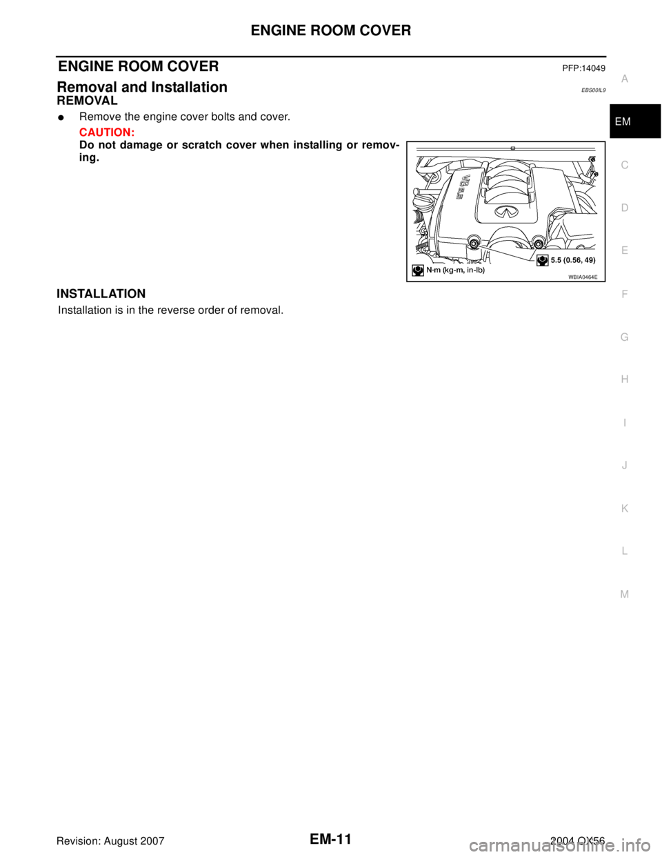
ENGINE ROOM COVERPFP:14049
Removal and InstallationEBS00IL9
REMOVAL
�Remove the engine cover bolts and cover.
CAUTION:
Do not damage or scratch cover when installing or remov-
ing.
INSTALLATION
Installation is in the reverse order of removal.
WBIA0464E
Page 1895 of 3371

EM-12Revision: August 2007
DRIVE BELTS
2004 QX56
DRIVE BELTSPFP:02117
Checking Drive BeltsEBS00ILA
WAR NIN G:
Be sure to perform when the engine is stopped.
1. Remove the air duct and resonator assembly when inspecting the drive belt. Refer to EM-14, "
Removal
and Installation" .
2. Make sure that the indicator (single line notch) of each auto tensioner is within the allowable working
range (between three line notches).
NOTE:
�Check the auto tensioner indication when the engine is cold.
�When the new drive belt is installed, the range should be as shown.
�The indicator notch is located on the moving side of the auto tensioner.
3. Visually check the entire belt for wear, damage or cracks.
4. If the indicator is out of allowable working range or belt is damaged, replace the belt.
Tension AdjustmentEBS00ILB
Belt tensioning is not necessary, as it is automatically adjusted by the auto tensioner.
Removal and InstallationEBS00ILC
DRIVE BELT
Removal
1. Remove the air duct and resonator assembly. Refer to EM-14, "Removal and Installation" .
2. Install Tool on auto tensioner pulley bolt, move in the direction of
arrow (loosening direction of tensioner) as shown.
CAUTION:
Avoid placing hand in a location where pinching may occur
if the tool accidentally comes off.
3. Remove the drive belt.
LBIA0391E
1. Drive belt 2. Power steering pump pulley 3. Generator pulley
4. Crankshaft pulley 5. A/C compressor 6. Idler pulley
7. Cooling fan pulley 8. Water pump pulley 9. Drive belt tensioner
Tool number : — (J-46535)
WBIA0537E
Page 1897 of 3371
EM-14Revision: August 2007
AIR CLEANER AND AIR DUCT
2004 QX56
AIR CLEANER AND AIR DUCTPFP:16500
Removal and InstallationEBS00ILE
REMOVAL
1. Remove the engine room cover using power tool. Refer to EM-14, "REMOVAL" .
2. Disconnect the harness connector from the air cleaner case (upper).
3. Remove the air duct and resonator assembly and air cleaner case.
�Add marks as necessary for easier installation.
INSTALLATION
Installation is in the reverse order of removal.
CHANGING AIR CLEANER FILTER
1. Remove the air duct and resonator assembly and air cleaner case (upper).
2. Remove the air cleaner filter from the air cleaner case.
3. Installation is in the reverse order of removal.
1. Air cleaner case (upper) 2. Air cleaner filter 3. Air cleaner case (lower)
4. Air duct and resonator assembly
WBIA0465E
Page 1898 of 3371
INTAKE MANIFOLD
EM-15
C
D
E
F
G
H
I
J
K
L
MA
EM
Revision: August 20072004 QX56
INTAKE MANIFOLDPFP:14003
Removal and InstallationEBS00ILF
REMOVAL
1. Partially drain the engine coolant. Refer to MA-12, "DRAINING ENGINE COOLANT" .
WAR NIN G:
To avoid the danger of being scalded, never drain the engine coolant when the engine is hot.
2. Remove the engine room cover using power tool. Refer to EM-11, "
REMOVAL" .
3. Release the fuel pressure. Refer to EC-46, "
FUEL PRESSURE RELEASE" .
4. Remove the air duct and resonator assembly. Refer to EM-14, "
REMOVAL" .
5. Disconnect the fuel tube quick connector on the engine side.
1. Intake manifold 2. PCV hose 3. Gasket
4. Electric throttle control actuator 5. Water hose 6. Water hose
7. PCV hose 8. EVAP hose 9. EVAP canister purge control sole-
noid valve
10. Bracket 11. Gasket
KBIA2461E
LBIA0395E
 TROUBLESHOOTING
EM-9
C
D
E
F
G
H
I
J
K
L
MA
EM
Revision: August 20072004 QX56
NOISE, VIBRATION, AND HARSHNESS (NVH) TROUBLESHOOTINGPFP:00003
NVH Troubleshooting �")