LT-154
ILLUMINATION
Revision: August 20072004 QX56
�to power liftgate switch terminal 4
�to front room/map lamp assembly (console box illumination) terminal 8
�to AV switch terminal 4
�to hazard switch terminal 4
�to audio unit terminal 7
�to rear sonar system OFF switch terminal 4
�to 4WD switch terminal 8 (with 4-wheel drive)
�to front air control terminal 24 and
�to rear power vent window switch terminal 6
�to DVD player terminal 10 (with DVD entertainment system)
�to pedal adjusting switch terminal 6
�to A/T device terminal 12
�to front heated seat switches terminal 6
�to VDC OFF switch terminal 4
�to tow mode switch terminal 4
�to headlamp aiming switch terminal 4
�to clock terminal 4 and
�to combination meter terminal 18.
Ground is supplied
�to illumination control switch terminal 3
�to glove box lamp terminal –
�to display control unit terminal 3
�to rear heated seat switches terminal 6
�to electric brake (pre-wiring) terminal 1 and
�to compass and thermometer terminal 7
�through grounds M57, M61 and M79, and
�to NAVI control unit terminal 30
�to rear air control terminal 3 and
�to rear audio remote control unit terminal 15
�through grounds B117 and B132.
With power and ground supplied, illumination lamps illuminate.
EXTERIOR LAMP BATTERY SAVER CONTROL
When the combination switch (lighting switch) is in the 1ST or 2ND position (or if auto light system is acti-
vated), and the ignition switch is turned from ON or ACC to OFF, the battery saver control function is activated.
Under this condition, the illumination lamps remain illuminated for 5 minutes, then the illumination lamps are
turned off.
When the lighting switch is turned from OFF to 1ST or 2ND position (or if auto light system is activated) after
illumination lamps are turned off by the battery saver control, the illumination lamps illuminate again.
Exterior lamp battery saver control mode can be changed by the function setting of CONSULT-II.
CAN Communication System DescriptionEKS007DB
Refer to LAN-5, "CAN COMMUNICATION" .
HARNESS
PG-61
C
D
E
F
G
H
I
J
L
MA
B
PG
Revision: August 20072004 QX56
Wiring Diagram Codes (Cell Codes)EKS007NZ
Use the chart below to find out what each wiring diagram code stands for.
Refer to the wiring diagram code in the alphabetical index to find the location (page number) of each wiring
diagram.
Code Section Wiring Diagram Name
A/C,A ATC Auto Air Conditioner
A/SUSP RSU Rear Air Suspension
AF1B1 EC Air Fuel Ratio Sensor 1 (Bank 1)
AF1B2 EC Air Fuel Ratio Sensor 1 (Bank 2)
AF1HB1 EC Air Fuel Ratio Sensor 1 (Bank 1)
AF1HB2 EC Air Fuel Ratio Sensor 1 (Bank 2)
APPS1 EC Accelerator Pedal Position Sensor
APPS2 EC Accelerator Pedal Position Sensor
APPS3 EC Accelerator Pedal Position Sensor
ASC/BS EC ASCD Brake Switch
ASC/SW EC ASCD Steering Switch
ASCBOF EC ASCD Brake Switch
ASCIND EC ASCD Indicator
A/T AT A/T Assembly
AT/IND DI A/T Indicator Lamp
AUDIO AV Audio
AUTO/DP SE Automatic Drive Positioner
AUTO/L LT Auto Light Control
B/CLOS BL Back Door Auto Closure System
BACK/L LT Back-up Lamp
BRK/SW EC Brake Switch
CAN EC CAN Communication Line
CAN LAN CAN System
CHARGE SC Charging System
CHIME DI Warning Chime
CLOCK DI Clock
COMBSW LT Combination Switch
COMM AV Audio Visual Communication System
COMPAS DI Compass and Thermometer
COOL/F EC Cooling Fan Control
D/LOCK BL Power Door Lock
DEF GW Rear Window Defogger
DTRL LT Headlamp - With Daytime Light System
DVD AV DVD Entertainment System
ECM/PW EC ECM Power Supply for Back-Up
ECTS EC Engine Coolant Temperature Sensor
ETC1 EC Electric Throttle Control Function
ETC2 EC Throttle Control Motor Relay
ETC3 EC Throttle Control Motor
F/FOG LT Front Fog Lamp
F/PUMP EC Fuel Pump
FTTS EC Fuel Tank Temperature Sensor
FUELB1 EC Fuel Injection System Bank 1
FUELB2 EC Fuel Injection System Bank 2
H/AIM LT Headlamp Aiming Control
H/LAMP LT Headlamp
HORN WW Horn
STEERING WHEEL
PS-7
C
D
E
F
H
I
J
K
L
MA
B
PS
Revision: August 20072004 QX56
STEERING WHEELPFP:48430
On-Vehicle Inspection and ServiceEGS000MQ
CHECKING CONDITION OF INSTALLATION
�Check installation condition of steering gear assembly, front suspension, axle and steering column.
�Check if movement exists when steering wheel is moved up and down, to the left and right and to the axial
direction.
�Check if the mounting nuts for steering gear assembly are loose.
Refer to PS-15, "
POWER STEERING GEAR AND LINKAGE" .
CHECKING STEERING WHEEL PLAY
1. Turn tires straight ahead, start engine, then turn steering wheel to the left and right lightly, and measure
steering wheel movement on the outer circumference when steering wheel is turned up to the point where
tires start moving.
CHECKING NEUTRAL POSITION ON STEERING WHEEL
�Check neutral position on steering wheel after confirming that front wheel alignment is correct. Refer to
FSU-6, "
Front Wheel Alignment" .
1. Turn tires straight ahead, check if steering wheel is in the neutral position.
2. If it is not in the neutral position, remove steering wheel and reinstall it correctly.
3. If the neutral position cannot be attained by repositioning the steering wheel two teeth or less on steering
stem, loosen tie-rod lock nuts of steering outer sockets, then adjust tie-rods by the same amount in the
opposite direction.
CHECKING STEERING WHEEL TURNING FORCE
1. Park vehicle on a level, dry surface and set parking brake.
2. Start engine.
3. Bring power steering fluid up to operating temperature of 60° – 80°C (140° – 176°F).
4. Tires need to be inflated to specified pressure. Refer to WT-33, "
Tire" .
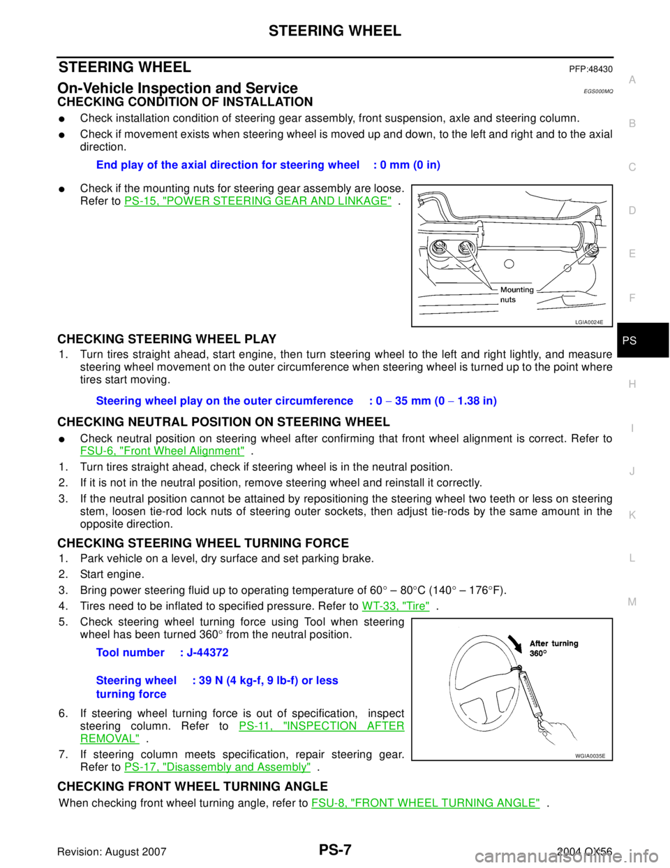
5. Check steering wheel turning force using Tool when steering
wheel has been turned 360° from the neutral position.
6. If steering wheel turning force is out of specification, inspect
steering column. Refer to PS-11, "
INSPECTION AFTER
REMOVAL" .
7. If steering column meets specification, repair steering gear.
Refer to PS-17, "
Disassembly and Assembly" .
CHECKING FRONT WHEEL TURNING ANGLE
When checking front wheel turning angle, refer to FSU-8, "FRONT WHEEL TURNING ANGLE" . End play of the axial direction for steering wheel : 0 mm (0 in)
LGIA0024E
Steering wheel play on the outer circumference : 0 − 35 mm (0 − 1.38 in)
Tool number : J-44372
Steering wheel
turning force: 39 N (4 kg-f, 9 lb-f) or less
WGIA0035E

EKS007NZ
Use the chart below to find out what each wiring diagram code stands for.
Refer to the")