Page 3030 of 3371

AUTOMATIC DRIVE POSITIONER
SE-81
C
D
E
F
G
H
J
K
L
MA
B
SE
Revision: August 20072004 QX56
3. CHECK MIRROR SENSOR GROUND CIRCUIT
1. Turn ignition switch OFF.
2. Check continuity between automatic drive positioner control unit
connector M34 terminal 41 and ground.
OK or NG
OK >> Check the condition of the harness and connector.
NG >> Replace automatic drive positioner control unit.
A/T Device (Detent Switch) Circuit InspectionEIS002Z9
1. CHECK FUNCTION
With CONSULT-II
Check that when the A/T shift lever is in P position, “DETENT SW”
on the DATA MONITOR becomes OFF.
Without CONSULT-II
GO TO 2.
OK or NG
OK >> A/T device (detent switch) circuit is OK.
NG >> GO TO 2.
2. CHECK A/T DEVICE (DETENT SWITCH) HARNESS
1. Turn ignition switch OFF.
2. Disconnect A/T device and driver seat control unit.
3. Check continuity between A/T device connector M203 terminal 6
and driver seat control unit connector P2 terminal 21.
4. Check continuity between A/T device connector M203 terminal 6
and ground.
OK or NG
OK >> GO TO 3.
NG >> Repair or replace harness.41 (W/G) - Ground : Continuity should exist.
LIIA1135E
Monitor item
[OPERATION or UNIT]Contents
DETENT SW“ON/
OFF”The selector lever position “P position (OFF)/other than P
position (ON)” judged from the park switch signal is dis-
played.
PIIA0291E
6 (L/R) - 21 (L/R) : Continuity should exist.
6 (L/R) - Ground : Continuity should not exist.
LIIA1024E
Page 3031 of 3371
 as follows.
OK or NG
OK >> A/T device is OK.
NG >> Replace")
SE-82
AUTOMATIC DRIVE POSITIONER
Revision: August 20072004 QX56
3. CHECK DETENTION SWITCH
Check continuity between A/T device (DETENT switch) as follows.
OK or NG
OK >> A/T device is OK.
NG >> Replace A/T device.
Steering Wheel Tilt Switch Circuit InspectionEIS0038N
1. CHECK FUNCTION
With CONSULT-II
With “TILT SW-UP, TILT SW-DOWN” on the DATA MONITOR, oper-
ate the ADP steering wheel tilt switch to check ON/OFF operation.
Without CONSULT-II
1. Turn ignition switch OFF.
2. Check voltage between automatic drive positioner control unit
connector and ground.
OK or NG
OK >> ADP steering wheel tilt switch circuit is OK.
NG >> GO TO 2.
Terminals
Condition Continuity
(+) (–)
56P position Continuity should not exist.
Other than
P positionContinuity should exist.
LIIA1491E
Monitor item [OPERATION or
UNIT]Contents
TILT SW-UP “ON/OFF”Operation (ON)/open (OFF) status
judged from the tilt switch (FR) signal is
displayed.
TILT SW-DOWN “ON/OFF”Operation (ON)/open (OFF) status
judged from the tilt switch (RR) signal is
displayed.
PIIA0315E
ConnectorTe r m i n a l s
(Wire color)
ConditionVoltage (V)
(Approx.)
(+) (–)
M331 (W/G)
GroundTilt switch ON (UP
operation)0
Other than above 5
17 (G/B)Tilt switch ON (DOWN
operation)0
Other than above 5
LIIA0491E
Page 3034 of 3371

AUTOMATIC DRIVE POSITIONER
SE-85
C
D
E
F
G
H
J
K
L
MA
B
SE
Revision: August 20072004 QX56
UART Communication Line Circuit InspectionEIS002ZB
1. CHECK UART LINE INPUT/OUTPUT SIGNAL 1
1. Turn ignition switch OFF.
2. Check signal between driver seat control unit connector and
ground, with oscilloscope.
OK or NG
OK >> GO TO 2.
NG >> Check the following.
�When voltage wave form does not appear with a constant voltage (approx. 5V), replace driver
seat control unit.
�When voltage wave form does not appear with a constant voltage (approx. 0V), replace auto-
matic driver seat control unit.
2. CHECK UART LINE INPUT/OUTPUT SIGNAL 2
Check signal between automatic drive positioner control unit con-
nector ground, with oscilloscope.
OK or NG
OK >> GO TO 3.
NG >> Check the following.
�When voltage wave form does not appear with a constant voltage (approx. 5V), replace auto-
matic drive positioner control unit.
�When voltage wave form does not appear with a constant voltage (approx. 0V), replace driver
seat control unit.
ConnectorTe r m i n a l s
(Wire color)
Condition Signal
(+) (–)
P2 17 (W) GroundPedal
adjusting
switch ON
(FOR-
WARD or
BACK-
WARD
operation)
PIIA4599E
PIIA4814E
ConnectorTe r m i n a l s
(Wire color)
Condition Signal
(+) (–)
M33 10 (L) GroundPedal
adjusting
switch ON
(FOR-
WARD or
BACK-
WARD
operation)
PIIA4816E
PIIA4813E
Page 3108 of 3371
SPIRAL CABLE
SRS-47
C
D
E
F
G
I
J
K
L
MA
B
SRS
Revision: August 20072004 QX56
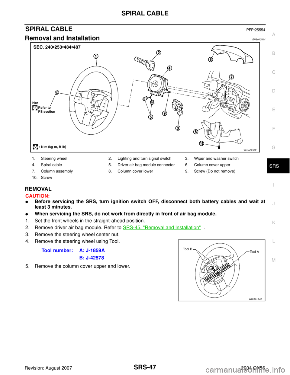
SPIRAL CABLEPFP:25554
Removal and InstallationEHS000WM
REMOVAL
CAUTION:
�Before servicing the SRS, turn ignition switch OFF, disconnect both battery cables and wait at
least 3 minutes.
�When servicing the SRS, do not work from directly in front of air bag module.
1. Set the front wheels in the straight-ahead position.
2. Remove driver air bag module. Refer to SRS-45, "
Removal and Installation" .
3. Remove the steering wheel center nut.
4. Remove the steering wheel using Tool.
5. Remove the column cover upper and lower.
WHIA0233E
1. Steering wheel 2. Lighting and turn signal switch 3. Wiper and washer switch
4. Spiral cable 5. Driver air bag module connector 6. Column cover upper
7. Column assembly 8. Column cover lower 9. Screw (Do not remove)
10. Screw
Tool number: A: J-1859A
B: J-42578
WHIA0124E
Page 3109 of 3371

SRS-48
SPIRAL CABLE
Revision: August 20072004 QX56
6. Remove wiper washer switch connector, then pinch the tabs at
wiper and washer switch base and slide switch away from steer-
ing column to remove.
7. While pressing tabs, pull lighting and turn signal switch toward
driver door and disconnect from base.
8. Remove the screws, release the clip, and remove the spiral
cable.
CAUTION:
�Do not disassemble spiral cable.
�Do not apply lubricant to the spiral cable.
9. Remove the spiral cable connectors.
CAUTION:
With the steering linkage disconnected, the spiral cable may snap by turning the steering wheel
beyond the limited number of turns. The spiral cable can be turned counterclockwise about 2.5
turns from the neutral position.
INSTALLATION
Installation is in the reverse order of removal.
�Align spiral cable correctly when installing steering wheel. Make
sure that the spiral cable is in the neutral position. The neutral
position is detected by turning left 2.6 revolutions from the right
end position and ending with the knob at the top.
�If equipped with VDC, refer to BRC-62, "Adjustment of Steering
Angle Sensor Neutral Position" for steering angle sensor
adjustment.
�After the work is completed, perform self-diagnosis to make sure
no malfunction is detected. Refer to SRS-20, "
SRS Operation
Check" .
LHIA0034E
LHIA0035E
LHIA0036E
WGIA0038E
Page 3133 of 3371
 “AIR BAG” and “SEAT
BELT PRE-TENSIONER”
EDS0017J
The Supplemental Rest")
TF-8
PRECAUTIONS
Revision: August 20072004 QX56
PRECAUTIONSPFP:00001
Precautions for Supplemental Restraint System (SRS) “AIR BAG” and “SEAT
BELT PRE-TENSIONER”
EDS0017J
The Supplemental Restraint System such as “AIR BAG” and “SEAT BELT PRE-TENSIONER”, used along
with a front seat belt, helps to reduce the risk or severity of injury to the driver and front passenger for certain
types of collision. This system includes seat belt switch inputs and dual stage front air bag modules. The SRS
system uses the seat belt switches to determine the front air bag deployment, and may only deploy one front
air bag, depending on the severity of a collision and whether the front occupants are belted or unbelted.
Information necessary to service the system safely is included in the SRS and SB section of this Service Man-
ual.
WAR NIN G:
�To avoid rendering the SRS inoperative, which could increase the risk of personal injury or death
in the event of a collision which would result in air bag inflation, all maintenance must be per-
formed by an authorized NISSAN/INFINITI dealer.
�Improper maintenance, including incorrect removal and installation of the SRS, can lead to per-
sonal injury caused by unintentional activation of the system. For removal of Spiral Cable and Air
Bag Module, see the SRS section.
�Do not use electrical test equipment on any circuit related to the SRS unless instructed to in this
Service Manual. SRS wiring harnesses can be identified by yellow and/or orange harnesses or
harness connectors.
PrecautionsEDS0017K
�Before connecting or disconnecting the transfer control
unit harness connector, turn ignition switch OFF and dis-
connect negative battery terminal. Failure to do so may
damage the transfer control unit. Because battery voltage is
applied to transfer control unit even if ignition switch is
turned off.
�When connecting or disconnecting pin connectors into or
from transfer control unit, take care not to damage pin ter-
minals (bend or break).
Make sure that there are not any bends or breaks on trans-
fer control unit pin terminal, when connecting pin connec-
tors.
�Before replacing transfer control unit, perform transfer con-
trol unit input/output signal inspection and make sure
whether transfer control unit functions properly or not. (See
page TF-55
.)
SEF 2 89 H
SEF 2 91 H
MEF040DB
Page 3156 of 3371
EDS002G7
CONSULT-II can display each diagnostic item using t")
ON BOARD DIAGNOSTIC SYSTEM DESCRIPTION
TF-31
C
E
F
G
H
I
J
K
L
MA
B
TF
Revision: August 20072004 QX56
CONSULT-II Function (ALL MODE AWD/4WD)EDS002G7
CONSULT-II can display each diagnostic item using the diagnostic test modes shown following.
Trouble Diagnosis with CONSULT-IIEDS0017V
SELF-DIAGNOSIS
CONSULT-II Setting Procedure
1. Turn ignition switch to “OFF” position.
CAUTION:
If CONSULT-II is used with no connection of CONSULT-II CONVERTER, malfunctions might be
detected in self-diagnosis depending on control unit which carry out CAN communication.
2. Connect CONSULT-II and CONSULT-II CONVERTER to data
link connector.
3. Start engine.
4. On CONSULT-II screen, touch “START (NISSAN BASED
VHCL)”.
5. Touch “ALL MODE AWD/4WD” on SELECT SYSTEM screen.
If "ALL MODE AWD/4WD" is not indicated, refer to GI-39,
"CONSULT-II Data Link Connector (DLC) Circuit" .
ALL MODE AWD/4WD diag-
nostic modeDescription
SELF-DIAG RESULTS Displays transfer control unit self-diagnosis results.
DATA MONITOR Displays transfer control unit input/output data in real time.
WORK SUPPORTSupports inspections and adjustments. Commands are transmitted to the transfer control unit for set-
ting the status suitable for required operation, input/output signals are received from the transfer con-
trol unit and received data is displayed.
CAN DIAG SUPPORT
MNTRThe results of transmit/receive diagnosis of CAN communication can be read.
ECU PART NUMBER Transfer control unit part number can be read.
BBIA0369E
BCIA0029E
BCIA0030E
Page 3160 of 3371

ON BOARD DIAGNOSTIC SYSTEM DESCRIPTION
TF-35
C
E
F
G
H
I
J
K
L
MA
B
TF
Revision: August 20072004 QX56
7. Touch “ECU INPUT SIGNALS” or “MAIN SIGNALS”.
8. Select “Numerical Display”, “Bar Chart Display” or “Line Graph
Display”.
9. Touch “SETTING” to set record conditions.
10. Touch “AUTO TRIG” or “MANU TRIG”.
11. Return to “SELECT MONITOR ITEM” on “DATA MONITOR”
screen and touch “START”.
12. Monitored data are displayed.
DATA MONITOR ITEMS
: Standard : Option
WDIA0084E
SAT9 7 3J
SMT963D
Item [Unit]Monitor item
Remarks ECU
INPUT
SIGNALSMAIN
SIGNALSSELEC-
TION
FROM
MENU
VHCL/SEN-FR [km/h], [MPH]Indicates average vehicle speed of ABS
front left/right wheel.
VHCL/SEN-RR [km/h], [MPH]Indicates average vehicle speed of ABS
rear left/right wheel.
Engine speed [rpm]—
Throttle position sensor—
Transfer fluid temperature sensor
[V]—
Battery voltage [V]—
2WD switch [ON-OFF] 2WD switch of 4WD shift switch
AUTO switch [ON-OFF] AUTO switch of 4WD shift switch
Lock switch [ON-OFF] 4H switch of 4WD shift switch
4L switch [ON-OFF] 4LO switch of 4WD shift switch