Page 3178 of 3371
TROUBLE DIAGNOSIS — BASIC INSPECTION
TF-53
C
E
F
G
H
I
J
K
L
MA
B
TF
Revision: August 20072004 QX56
3. CRUISE TEST
1. INSPECTION START
Do you have CONSULT-II?
Ye s o r N o
Yes >> GO TO 2.
No >> GO TO 3.
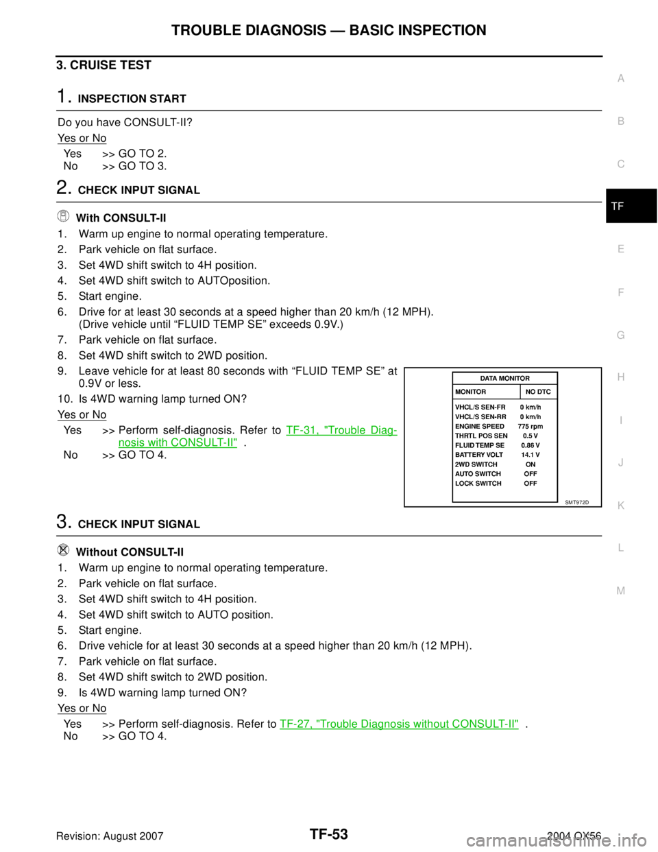
2. CHECK INPUT SIGNAL
With CONSULT-II
1. Warm up engine to normal operating temperature.
2. Park vehicle on flat surface.
3. Set 4WD shift switch to 4H position.
4. Set 4WD shift switch to AUTOposition.
5. Start engine.
6. Drive for at least 30 seconds at a speed higher than 20 km/h (12 MPH).
(Drive vehicle until “FLUID TEMP SE” exceeds 0.9V.)
7. Park vehicle on flat surface.
8. Set 4WD shift switch to 2WD position.
9. Leave vehicle for at least 80 seconds with “FLUID TEMP SE” at
0.9V or less.
10. Is 4WD warning lamp turned ON?
Ye s o r N o
Yes >> Perform self-diagnosis. Refer to TF-31, "Trouble Diag-
nosis with CONSULT-II" .
No >> GO TO 4.
3. CHECK INPUT SIGNAL
Without CONSULT-II
1. Warm up engine to normal operating temperature.
2. Park vehicle on flat surface.
3. Set 4WD shift switch to 4H position.
4. Set 4WD shift switch to AUTO position.
5. Start engine.
6. Drive vehicle for at least 30 seconds at a speed higher than 20 km/h (12 MPH).
7. Park vehicle on flat surface.
8. Set 4WD shift switch to 2WD position.
9. Is 4WD warning lamp turned ON?
Ye s o r N o
Yes >> Perform self-diagnosis. Refer to TF-27, "Trouble Diagnosis without CONSULT-II" .
No >> GO TO 4.
SMT972D
Page 3188 of 3371
2-4WD SHIFT SOLENOID VALVE AND 4WD SHIFT SWITCH
TF-63
C
E
F
G
H
I
J
K
L
MA
B
TF
Revision: August 20072004 QX56
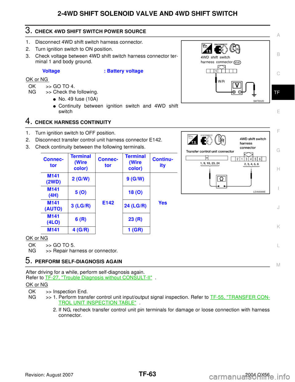
3. CHECK 4WD SHIFT SWITCH POWER SOURCE
1. Disconnect 4WD shift switch harness connector.
2. Turn ignition switch to ON position.
3. Check voltage between 4WD shift switch harness connector ter-
minal 1 and body ground.
OK or NG
OK >> GO TO 4.
NG >> Check the following.
�No. 49 fuse (10A)
�Continuity between ignition switch and 4WD shift
switch
4. CHECK HARNESS CONTINUITY
1. Turn ignition switch to OFF position.
2. Disconnect transfer control unit harness connector E142.
3. Check continuity between the following terminals.
OK or NG
OK >> GO TO 5.
NG >> Repair harness or connector.
5. PERFORM SELF-DIAGNOSIS AGAIN
After driving for a while, perform self-diagnosis again.
Refer to TF-27, "
Trouble Diagnosis without CONSULT-II" .
OK or NG
OK >> Inspection End.
NG >> 1. Perform transfer control unit input/output signal inspection. Refer to TF-55, "
TRANSFER CON-
TROL UNIT INSPECTION TABLE" .
2. If NG, recheck transfer control unit pin terminals for damage or loose connection with harness
connector. Voltage : Battery voltage
SMT852D
Connec-
torTe r m i n a l
(Wire
color)Connec-
torTe r m i na l
(Wire
color)Continu-
ity
M141
(2WD)2 (G/W)
E1429 (G/W)
Yes M141
(4H)5 (O) 18 (O)
M141
(AUTO)3 (LG/R) 24 (LG/R)
M141
(4LO)6 (R) 23 (R)
M141 4 (G/R) 1 (GR)
LDIA0069E
Page 3189 of 3371

TF-64
TRANSFER MOTOR AND TRANSFER MOTOR RELAY
Revision: August 20072004 QX56
TRANSFER MOTOR AND TRANSFER MOTOR RELAYPFP:00000
Diagnostic ProcedureEDS00185
1. CHECK TRANSFER MOTOR AND TRANSFER MOTOR RELAY
Refer to TF-96, "
TRANSFER MOTOR" and TF-97, "TRANSFER
MOTOR RELAY" .
OK or NG
OK >> GO TO 2.
NG >> Replace transfer motor or transfer motor relay.
2. CHECK INPUT SIGNAL
With CONSULT-II
1. Select “MAIN SIGNALS” in Data Monitor.
2. Read out ON/OFF status of “MOTOR RELAY”.
3. When the value is different from standard value although ON/
OFF switching occurs, check the following items.
�PNP switch and throttle position sensor circuits
Refer to AT-109, "
DTC P0705 PARK/NEUTRAL POSITION
SWITCH" , AT-129, "DTC P1705 THROTTLE POSITION SEN-
SOR" .
OK or NG
OK >> GO TO 3.
NG >> 1. Perform transfer control unit input/output signal
inspection. Refer to TF-55, "
TRANSFER CONTROL UNIT INSPECTION TABLE" .
2. If NG, recheck transfer control unit pin terminals for damage or loose connection with harness
connector.
3. CHECK TRANSFER MOTOR RELAY POWER SOURCE
1. Disconnect transfer motor relay harness connectors E153 and
E154.
2. Turn ignition switch to ON position.
3. Check voltage between transfer motor relay harness connector
E153 terminal 5 (G/R), E154 terminal 2 (Y/R), and ground.
OK or NG
OK >> GO TO 4.
NG >> Check the following.
�No. 58 fuse (20A)
�No. 49 fuse (10A)
�Harness continuity between ignition switch and No. 58 fuse (20A) and No. 49 fuse (10A).
�Harness continuity between fuse and transfer motor relay.
LDIA0102E
SMT975D
Voltage : Battery voltage
LDIA0070E
Page 3190 of 3371
TRANSFER MOTOR AND TRANSFER MOTOR RELAY
TF-65
C
E
F
G
H
I
J
K
L
MA
B
TF
Revision: August 20072004 QX56
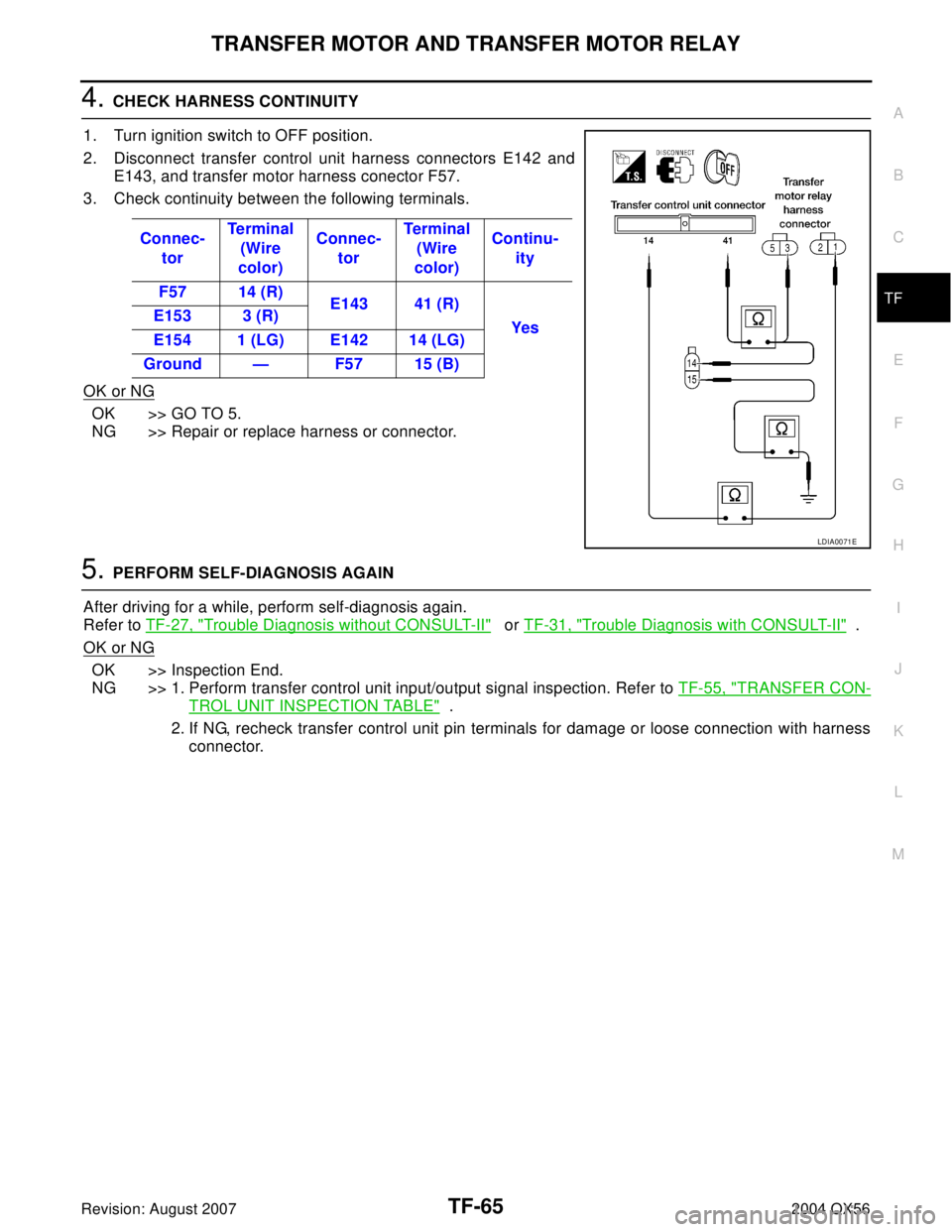
4. CHECK HARNESS CONTINUITY
1. Turn ignition switch to OFF position.
2. Disconnect transfer control unit harness connectors E142 and
E143, and transfer motor harness conector F57.
3. Check continuity between the following terminals.
OK or NG
OK >> GO TO 5.
NG >> Repair or replace harness or connector.
5. PERFORM SELF-DIAGNOSIS AGAIN
After driving for a while, perform self-diagnosis again.
Refer to TF-27, "
Trouble Diagnosis without CONSULT-II" or TF-31, "Trouble Diagnosis with CONSULT-II" .
OK or NG
OK >> Inspection End.
NG >> 1. Perform transfer control unit input/output signal inspection. Refer to TF-55, "
TRANSFER CON-
TROL UNIT INSPECTION TABLE" .
2. If NG, recheck transfer control unit pin terminals for damage or loose connection with harness
connector. Connec-
torTe r m i n a l
(Wire
color)Connec-
torTe r m i na l
(Wire
color)Continu-
ity
F57 14 (R)
E143 41 (R)
Yes E153 3 (R)
E154 1 (LG) E142 14 (LG)
Ground — F57 15 (B)
LDIA0071E
Page 3193 of 3371
TF-68
TRANSFER FLUID TEMPERATURE SENSOR
Revision: August 20072004 QX56
4. CHECK INPUT SIGNAL
Without CONSULT-II
1. Turn ignition switch to ON position.
2. Check voltage between transfer control unit harness connector
E143 terminals 28 (B/G) and 31(G).
OK or NG
OK >> GO TO 5.
NG >> Check the following.
�Continuity between transfer control unit and transfer
terminal cord assembly harness connector
5. PERFORM SELF-DIAGNOSIS AGAIN
After driving for a while, perform self-diagnosis again.
Refer to TF-27, "
Trouble Diagnosis without CONSULT-II" .
OK or NG
OK >> Inspection End.
NG >> 1. Perform transfer control unit input/output signal inspection. Refer to TF-55, "
TRANSFER CON-
TROL UNIT INSPECTION TABLE" .
2. If NG, recheck transfer control unit pin terminals for damage or loose connection with harness
connector.Vo l ta g e
20°C (68°F) : Approx. 1.1V
80°C (176°F) : Approx. 0.3V
LDIA0072E
Page 3196 of 3371
ATP SWITCH, WAIT DETECTION SWITCH AND NEUTRAL-4LO SWITCH
TF-71
C
E
F
G
H
I
J
K
L
MA
B
TF
Revision: August 20072004 QX56
6. CHECK SWITCH POWER SOURCE
Without CONSULT-II
1. Turn ignition switch to ON position.
2. Disconnect ATP switch F55, neutral-4LO switch F60, and wait detection switch F59 harness connectors.
3. Check voltage between the following terminals.
OK or NG
OK >> Inspection End.
NG >> GO TO 7.
7. PERFORM SELF-DIAGNOSIS AGAIN
After driving for a while, perform self-diagnosis again.
Refer to TF-27, "
Trouble Diagnosis without CONSULT-II" .
OK or NG
OK >> Inspection End.
NG >> 1. Perform transfer control unit input/output signal inspection. Refer to TF-55, "
TRANSFER CON-
TROL UNIT INSPECTION TABLE" .
2. If NG, recheck transfer control unit pin terminals for damage or loose connection with harness
connector. ConnectorTe r m i n a l
(Wire color)Battery
voltage
E14340 (L)
Ground Yes 25 (V)
43 (G/Y)
WDIA0059E
Page 3198 of 3371
CLUTCH PRESSURE SWITCH
TF-73
C
E
F
G
H
I
J
K
L
MA
B
TF
Revision: August 20072004 QX56
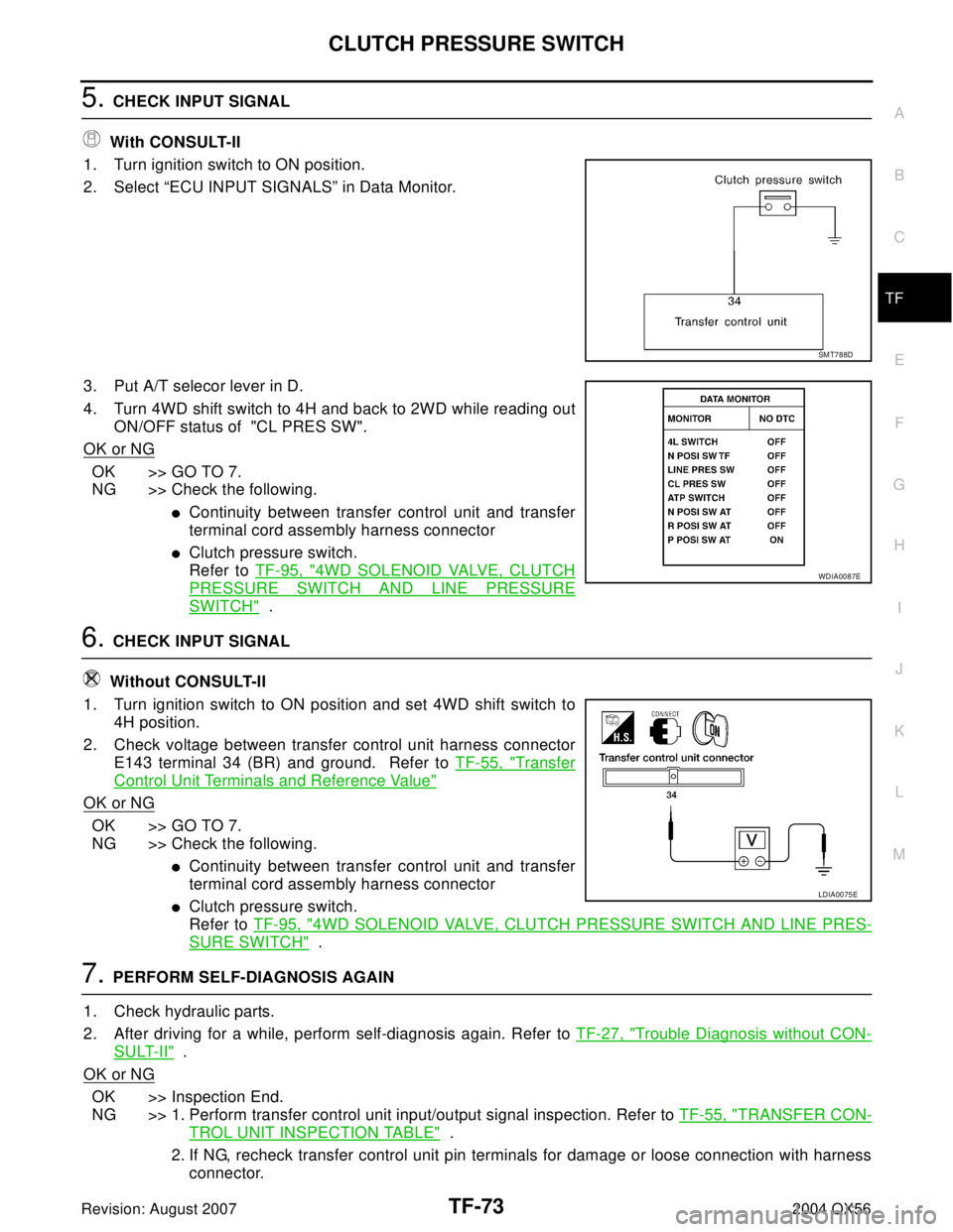
5. CHECK INPUT SIGNAL
With CONSULT-II
1. Turn ignition switch to ON position.
2. Select “ECU INPUT SIGNALS” in Data Monitor.
3. Put A/T selecor lever in D.
4. Turn 4WD shift switch to 4H and back to 2WD while reading out
ON/OFF status of "CL PRES SW".
OK or NG
OK >> GO TO 7.
NG >> Check the following.
�Continuity between transfer control unit and transfer
terminal cord assembly harness connector
�Clutch pressure switch.
Refer to TF-95, "
4WD SOLENOID VALVE, CLUTCH
PRESSURE SWITCH AND LINE PRESSURE
SWITCH" .
6. CHECK INPUT SIGNAL
Without CONSULT-II
1. Turn ignition switch to ON position and set 4WD shift switch to
4H position.
2. Check voltage between transfer control unit harness connector
E143 terminal 34 (BR) and ground. Refer to TF-55, "
Transfer
Control Unit Terminals and Reference Value"
OK or NG
OK >> GO TO 7.
NG >> Check the following.
�Continuity between transfer control unit and transfer
terminal cord assembly harness connector
�Clutch pressure switch.
Refer to TF-95, "
4WD SOLENOID VALVE, CLUTCH PRESSURE SWITCH AND LINE PRES-
SURE SWITCH" .
7. PERFORM SELF-DIAGNOSIS AGAIN
1. Check hydraulic parts.
2. After driving for a while, perform self-diagnosis again. Refer to TF-27, "
Trouble Diagnosis without CON-
SULT-II" .
OK or NG
OK >> Inspection End.
NG >> 1. Perform transfer control unit input/output signal inspection. Refer to TF-55, "
TRANSFER CON-
TROL UNIT INSPECTION TABLE" .
2. If NG, recheck transfer control unit pin terminals for damage or loose connection with harness
connector.
SMT788D
WDIA0087E
LDIA0075E
Page 3199 of 3371
TF-74
LINE PRESSURE SWITCH
Revision: August 20072004 QX56
LINE PRESSURE SWITCHPFP:00000
Diagnostic ProcedureEDS00189
1. CHECK MALFUNCTION
Is this malfunction detected only while driving in reverse?
Ye s o r N o
Yes >> Check A/T PNP switch “R” position.
�Refer to AT-109, "DTC P0705 PARK/NEUTRAL POSITION SWITCH" .
No >> GO TO 2.
2. CHECK OTHER MALFUNCTIONS
Are other malfunctions also detected by self-diagnosis and CONSULT-II?
Refer to TF-27, "
Trouble Diagnosis without CONSULT-II" and TF-31, "Trouble Diagnosis with CONSULT-II" .
Ye s o r N o
Yes >> Check for other malfunctions.
�(When other malfunctions are eliminated, line pressure switch malfunction display may disap-
pear.)
No >> GO TO 3.
3. CHECK INPUT SIGNAL
Do you have CONSULT-II?
Ye s o r N O
Yes >> GO TO 4.
No >> GO TO 5.
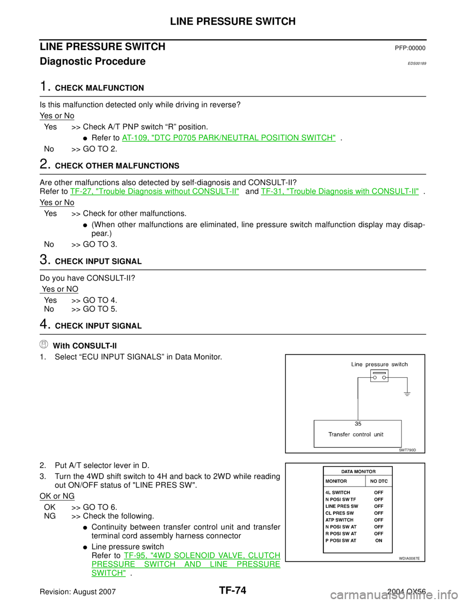
4. CHECK INPUT SIGNAL
With CONSULT-II
1. Select “ECU INPUT SIGNALS” in Data Monitor.
2. Put A/T selector lever in D.
3. Turn the 4WD shift switch to 4H and back to 2WD while reading
out ON/OFF status of "LINE PRES SW".
OK or NG
OK >> GO TO 6.
NG >> Check the following.
�Continuity between transfer control unit and transfer
terminal cord assembly harness connector
�Line pressure switch
Refer to TF-95, "
4WD SOLENOID VALVE, CLUTCH
PRESSURE SWITCH AND LINE PRESSURE
SWITCH" .
SMT790D
WDIA0087E