Page 2891 of 3371

RSU-32
REAR SUSPENSION MEMBER
Revision: August 20072004 QX56
4. Disconnect the rear load leveling air suspension hoses at the
rear load leveling air suspension compressor assembly.
�To disconnect the hoses, push in on the lock ring using a suit-
able tool and pull the hose out.
5. Remove both of the rear wheel and tire assemblies using power
tool.
6. Remove the brake caliper without disconnecting the brake
hoses, using power tool. Reposition the brake caliper out of the
way using a suitable wire. Refer to BR-28, "
Removal and Instal-
lation of Brake Caliper Assembly and Disc Rotor" .
CAUTION:
�Do not crimp or stretch the brake hose when repositioning the brake caliper out of the way.
�Do not press brake pedal while the brake caliper is removed.
7. Remove the spare tire.
8. Disconnect the two rear ABS sensor electrical connectors.
9. Remove the two rear drive shafts. Refer to RAX-7, "
Removal and Installation" .
10. Remove the rear final drive. Refer to RFD-10, "
REAR FINAL DRIVE ASSEMBLY" .
11. Remove the EVAP canister bolt from the top of the rear suspension member.
12. Disconnect the parking brake cables from the brackets on the rear suspension member.
13. Set a suitable jack to support each of the rear lower links and the
coil spring tension.
14. Remove both of the rear lower link outer bolts and lower the jack to remove the rear coil springs.
15. Remove the two bolts to disconnect the seat belt latch anchor
from the rear suspension member.
16. Disconnect both of the connecting rods from the rear stabilizer
bar.
17. Set a suitable jack under the rear suspension member.
18. Remove the six rear suspension member bolts.
19. Slowly lower the jack to remove the rear suspension member,
suspension arm, front and rear lower links and stabilizer bar as
an assembly.
20. If necessary, remove the suspension arm, spare tire bracket,
height sensor, rear load leveling air suspension hoses, stabilizer
bar, knuckle, and front and rear lower links from the rear suspension member.
INSPECTION AFTER REMOVAL
Check the rear suspension member for deformation, cracks, and other damage and replace if necessary.
LEIA0074E
LEIA0077E
LEIA0075E
Page 2892 of 3371
REAR SUSPENSION MEMBER
RSU-33
C
D
F
G
H
I
J
K
L
MA
B
RSU
Revision: August 20072004 QX56
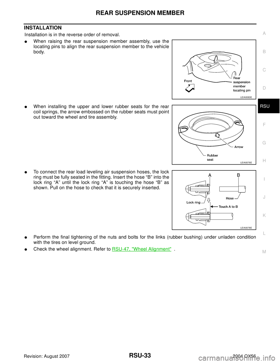
INSTALLATION
Installation is in the reverse order of removal.
�When raising the rear suspension member assembly, use the
locating pins to align the rear suspension member to the vehicle
body.
�When installing the upper and lower rubber seats for the rear
coil springs, the arrow embossed on the rubber seats must point
out toward the wheel and tire assembly.
�To connect the rear load leveling air suspension hoses, the lock
ring must be fully seated in the fitting. Insert the hose “B” into the
lock ring “A” until the lock ring “A” is touching the hose “B” as
shown. Pull on the hose to check that it is securely inserted.
�Perform the final tightening of the nuts and bolts for the links (rubber bushing) under unladen condition
with the tires on level ground.
�Check the wheel alignment. Refer to RSU-47, "Wheel Alignment" .
LEIA0083E
LEIA0076E
LEIA0078E
Page 2893 of 3371

RSU-34
SHOCK ABSORBER
Revision: August 20072004 QX56
SHOCK ABSORBERPFP:56210
Removal and Installation EES0011J
REMOVAL
1. Remove the wheel and tire assembly using power tool. Refer to WT-6, "Rotation" .
2. Use CONSULT-II “EXHAUST SOLENOID” active test to release the air pressure from the rear load level-
ing air suspension system.
3. Remove the four clips and remove the rear fender protector, front.
4. Disconnect the rear load leveling air suspension hose from the
shock absorber.
�To disconnect the hose, push in on the lock ring using a suit-
able tool and pull the air hose out.
5. Remove the shock absorber upper and lower end bolts using
power tool.
6. Remove the shock absorber.
CAUTION:
Do not damage the rubber boot on the shock absorber.
INSTALLATION
Installation is in the reverse order of removal.
�Tighten the shock absorber bolts to specification. Refer to RSU-25, "Components" .
INSPECTION AFTER INSTALLATION
�Check the shock absorber for any air leaks or damage to the rubber boot.
�Check the shock absorber for smooth operation through a full stroke, both compression and extension.
�Check piston rod for cracks, deformation or other damage and replace if necessary.
LEIA0081E
LEIA0082E
Page 2895 of 3371
RSU-36
SUSPENSION ARM
Revision: August 20072004 QX56
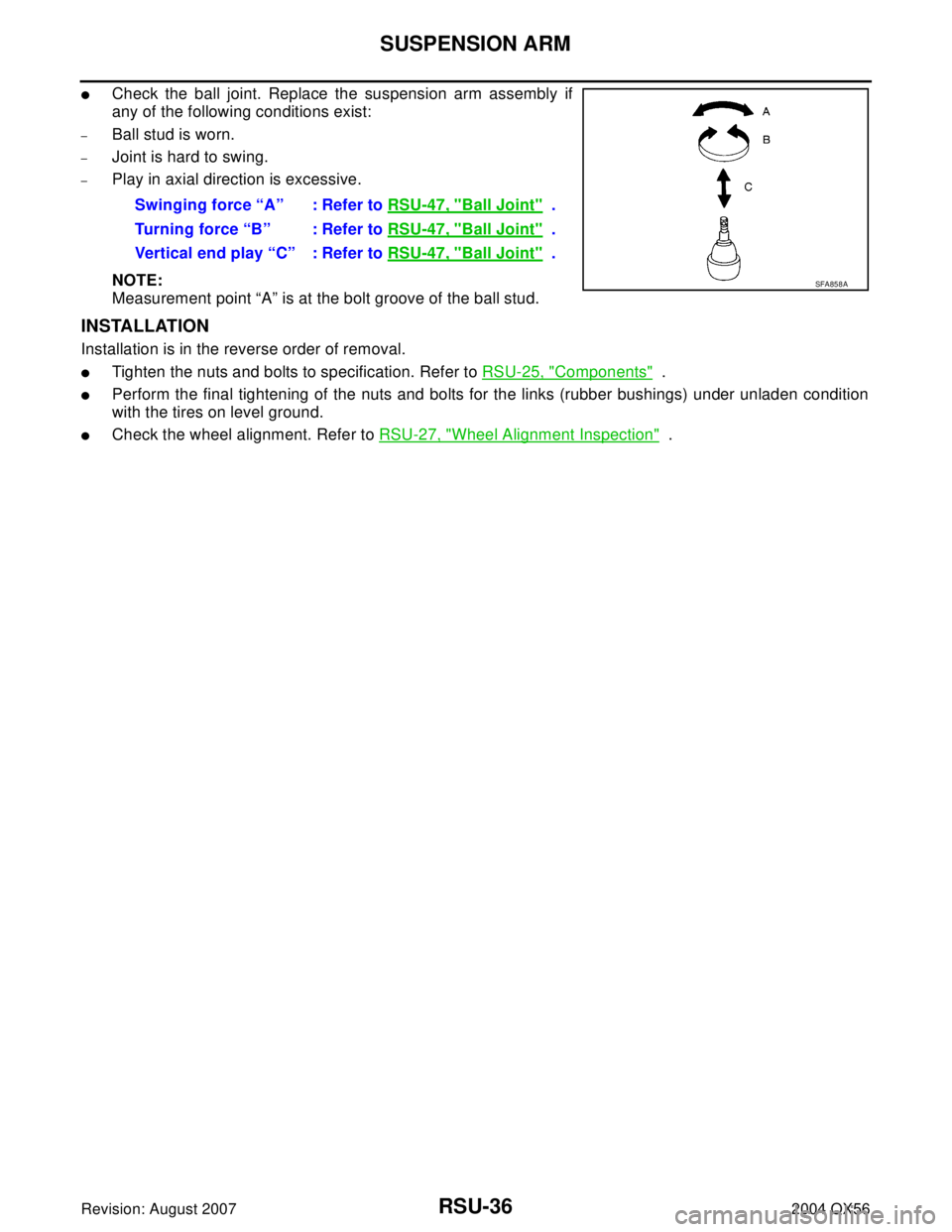
�Check the ball joint. Replace the suspension arm assembly if
any of the following conditions exist:
–Ball stud is worn.
–Joint is hard to swing.
–Play in axial direction is excessive.
NOTE:
Measurement point “A” is at the bolt groove of the ball stud.
INSTALLATION
Installation is in the reverse order of removal.
�Tighten the nuts and bolts to specification. Refer to RSU-25, "Components" .
�Perform the final tightening of the nuts and bolts for the links (rubber bushings) under unladen condition
with the tires on level ground.
�Check the wheel alignment. Refer to RSU-27, "Wheel Alignment Inspection" . Swinging force “A” : Refer to RSU-47, "
Ball Joint" .
Turning force “B” : Refer to RSU-47, "
Ball Joint" .
Vertical end play “C” : Refer to RSU-47, "
Ball Joint" .
SFA858A
Page 2897 of 3371
RSU-38
FRONT LOWER LINK
Revision: August 20072004 QX56
NOTE:
Measurement point “A” is at the bolt groove of the ball stud.
INSTALLATION
Installation is in the reverse order of removal.
�Tighten the nuts and bolts to specification. Refer to RSU-25, "Components" .
�Perform the final tightening of the front lower link nuts and bolts (with rubber bushings) under unladen
condition with tires on level ground.
�Check the wheel alignment. Refer to RSU-27, "Wheel Alignment Inspection" .
Page 2899 of 3371
RSU-40
REAR LOWER LINK & COIL SPRING
Revision: August 20072004 QX56
8. Remove the rear lower link adjusting bolt and nut from the rear
suspension member using power tool, then remove the rear
lower link.
INSPECTION AFTER REMOVAL
Check the coil spring and rubber seats for deformation, cracks, or other damage and replace if necessary.
INSTALLATION
Installation is in the reverse order of removal.
�Tighten the nuts and bolts to specification. Refer to RSU-25, "Components" .
�When installing the upper and lower rubber seats for the rear
coil springs, the arrow embossed on the rubber seats must point
out toward the wheel and tire assembly.
�After installing the rear lower link and coil spring, check the
wheel alignment and adjust if necessary. Refer to RSU-27,
"Wheel Alignment Inspection" .
LEIA0009E
LEIA0076E
Page 3106 of 3371

DRIVER AIR BAG MODULE
SRS-45
C
D
E
F
G
I
J
K
L
MA
B
SRS
Revision: August 20072004 QX56
DRIVER AIR BAG MODULEPFP:K8510
Removal and InstallationEHS000WL
REMOVAL
CAUTION:
�Do not attempt to repair or replace damaged direct-connect SRS component connectors. If a
driver air bag direct-connect harness connector is damaged, the spiral cable must be replaced.
�Before servicing the SRS, turn ignition switch OFF, disconnect both battery cables and wait at
least 3 minutes.
�When servicing the SRS, do not work from directly in front of air bag module.
1. Remove the left and right side lids and bolts.
2. Lift the driver air bag module from the steering wheel.
3. Disconnect the horn connector and air bag harness, then remove the driver air bag module.
�For removal/installation of the direct-connect SRS connectors, refer to SRS-7, "Direct-connect SRS
Component Connectors" .
CAUTION:
�When servicing the SRS, do not work from directly in front of air bag module.
1. Horn harness 2. Steering wheel hook 3. Inflator harness
4. Side lids RH/LH 5. Driver air bag module 6. Steering wheel
WHIA0159E
WHIA0184E