Page 2646 of 3371
CHASSIS AND BODY MAINTENANCE
MA-29
C
D
E
F
G
H
I
J
K
MA
B
MA
Revision: August 20072004 QX56
Checking Power Steering Fluid and LinesELS0010U
CHECKING FLUID LEVEL
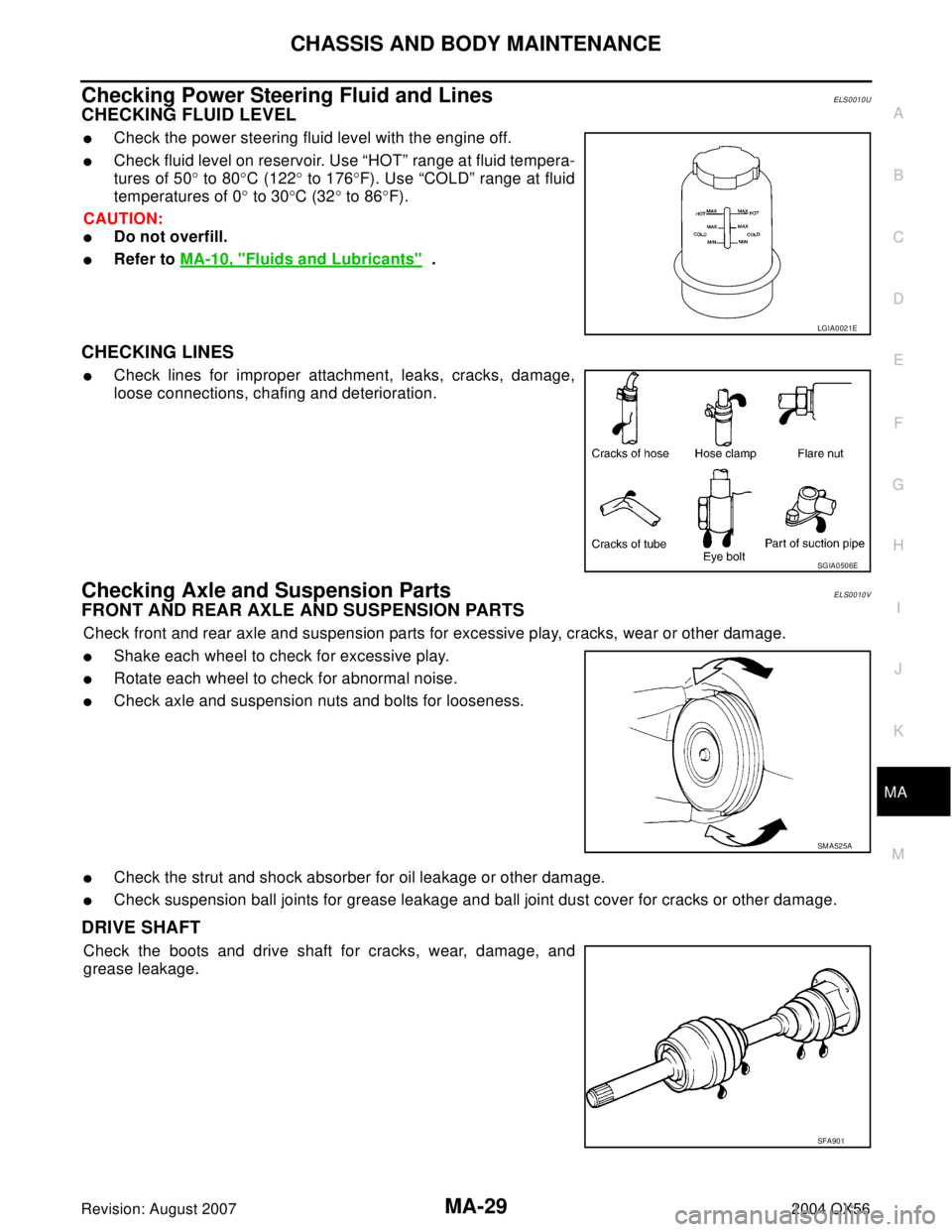
�Check the power steering fluid level with the engine off.
�Check fluid level on reservoir. Use “HOT” range at fluid tempera-
tures of 50° to 80°C (122° to 176°F). Use “COLD” range at fluid
temperatures of 0° to 30°C (32° to 86°F).
CAUTION:
�Do not overfill.
�Refer to MA-10, "Fluids and Lubricants" .
CHECKING LINES
�Check lines for improper attachment, leaks, cracks, damage,
loose connections, chafing and deterioration.
Checking Axle and Suspension PartsELS0010V
FRONT AND REAR AXLE AND SUSPENSION PARTS
Check front and rear axle and suspension parts for excessive play, cracks, wear or other damage.
�Shake each wheel to check for excessive play.
�Rotate each wheel to check for abnormal noise.
�Check axle and suspension nuts and bolts for looseness.
�Check the strut and shock absorber for oil leakage or other damage.
�Check suspension ball joints for grease leakage and ball joint dust cover for cracks or other damage.
DRIVE SHAFT
Check the boots and drive shaft for cracks, wear, damage, and
grease leakage.
LGIA0021E
SGIA0506E
SM A52 5A
SFA90 1
Page 2755 of 3371
PS-4
PREPARATION
Revision: August 20072004 QX56
Commercial Service ToolsEGS000ML
1. KV48105300-4 and 5295262U10
( — )
Connector A and O-ring
2. KV48105300-3 and 5295262U00
( — )
Eye-bolt and O-ring
3. KV48103500
(J26357 and J26357-10)
Pressure gauge and shut-off valve
4. KV48105300-1 and 5295262U00
( — )
Connector B and O-ring
5. KV48105300-2
( — )
NutMeasuring oil pump relief pressure
KV481J0010
(J-1859A)
Steering wheel pullerRemoving steering wheel
KV481J0020
(J-42578)
Steering wheel puller legsRemoving steering wheel
KV40107300
(—)Crimping boot bands
—
(J-44372)
Spring gaugeMeasuring steering wheel turning force Tool number
(Kent-Moore No.)
Tool nameDescription
SGIA0427E
LHIA0043E
LHIA0044E
ZZA1229D
LST024
Tool nameDescription
Power toolRemoving nuts and bolts
PBIC0190E
Page 2763 of 3371
PS-12
STEERING COLUMN
Revision: August 20072004 QX56
CAUTION:
�When installing the steering column, finger-tighten all of the lower bracket and joint retaining
bolts; then tighten them to specification. Do not apply undue stress to the steering column.
�The lower nut on the upper joint may not be reused.
NOTE:
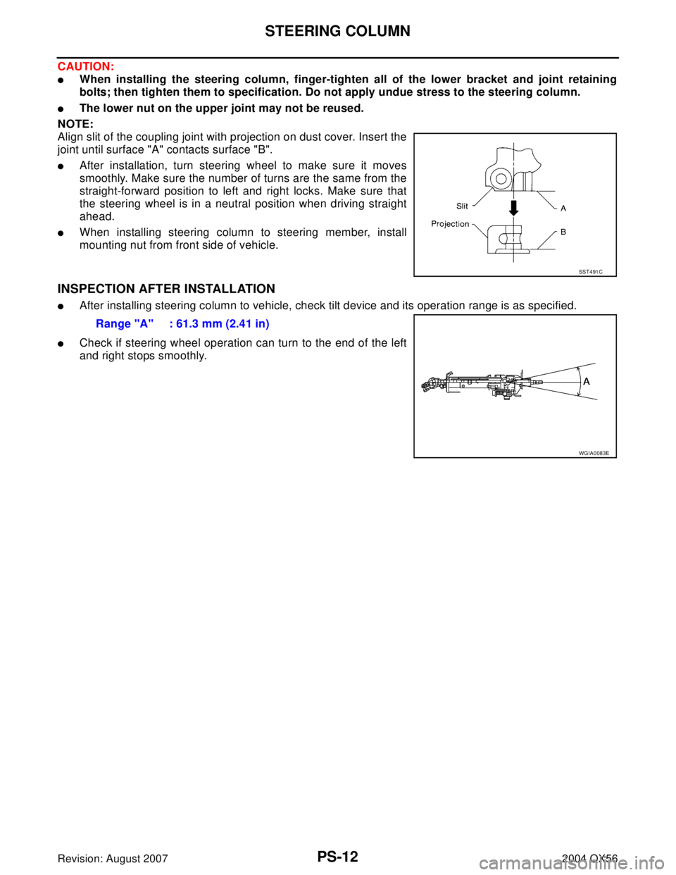
Align slit of the coupling joint with projection on dust cover. Insert the
joint until surface "A" contacts surface "B".
�After installation, turn steering wheel to make sure it moves
smoothly. Make sure the number of turns are the same from the
straight-forward position to left and right locks. Make sure that
the steering wheel is in a neutral position when driving straight
ahead.
�When installing steering column to steering member, install
mounting nut from front side of vehicle.
INSPECTION AFTER INSTALLATION
�After installing steering column to vehicle, check tilt device and its operation range is as specified.
�Check if steering wheel operation can turn to the end of the left
and right stops smoothly.
SST 4 91 C
Range "A" : 61.3 mm (2.41 in)
WGIA0083E
Page 2767 of 3371
PS-16
POWER STEERING GEAR AND LINKAGE
Revision: August 20072004 QX56
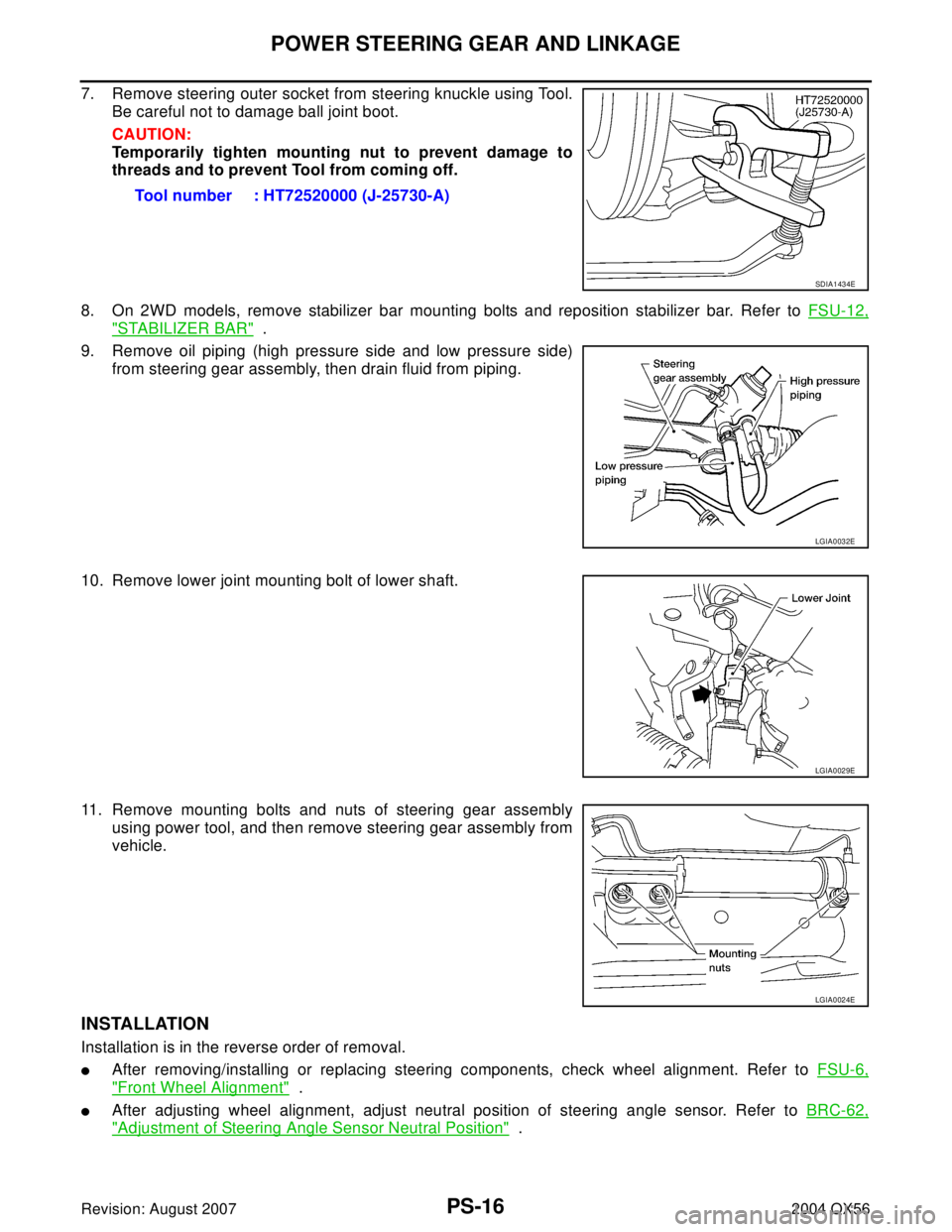
7. Remove steering outer socket from steering knuckle using Tool.
Be careful not to damage ball joint boot.
CAUTION:
Temporarily tighten mounting nut to prevent damage to
threads and to prevent Tool from coming off.
8. On 2WD models, remove stabilizer bar mounting bolts and reposition stabilizer bar. Refer to FSU-12,
"STABILIZER BAR" .
9. Remove oil piping (high pressure side and low pressure side)
from steering gear assembly, then drain fluid from piping.
10. Remove lower joint mounting bolt of lower shaft.
11. Remove mounting bolts and nuts of steering gear assembly
using power tool, and then remove steering gear assembly from
vehicle.
INSTALLATION
Installation is in the reverse order of removal.
�After removing/installing or replacing steering components, check wheel alignment. Refer to FSU-6,
"Front Wheel Alignment" .
�After adjusting wheel alignment, adjust neutral position of steering angle sensor. Refer to BRC-62,
"Adjustment of Steering Angle Sensor Neutral Position" . Tool number : HT72520000 (J-25730-A)
SDIA1434E
LGIA0032E
LGIA0029E
LGIA0024E
Page 2793 of 3371
RAX-6
WHEEL HUB
Revision: August 20072004 QX56
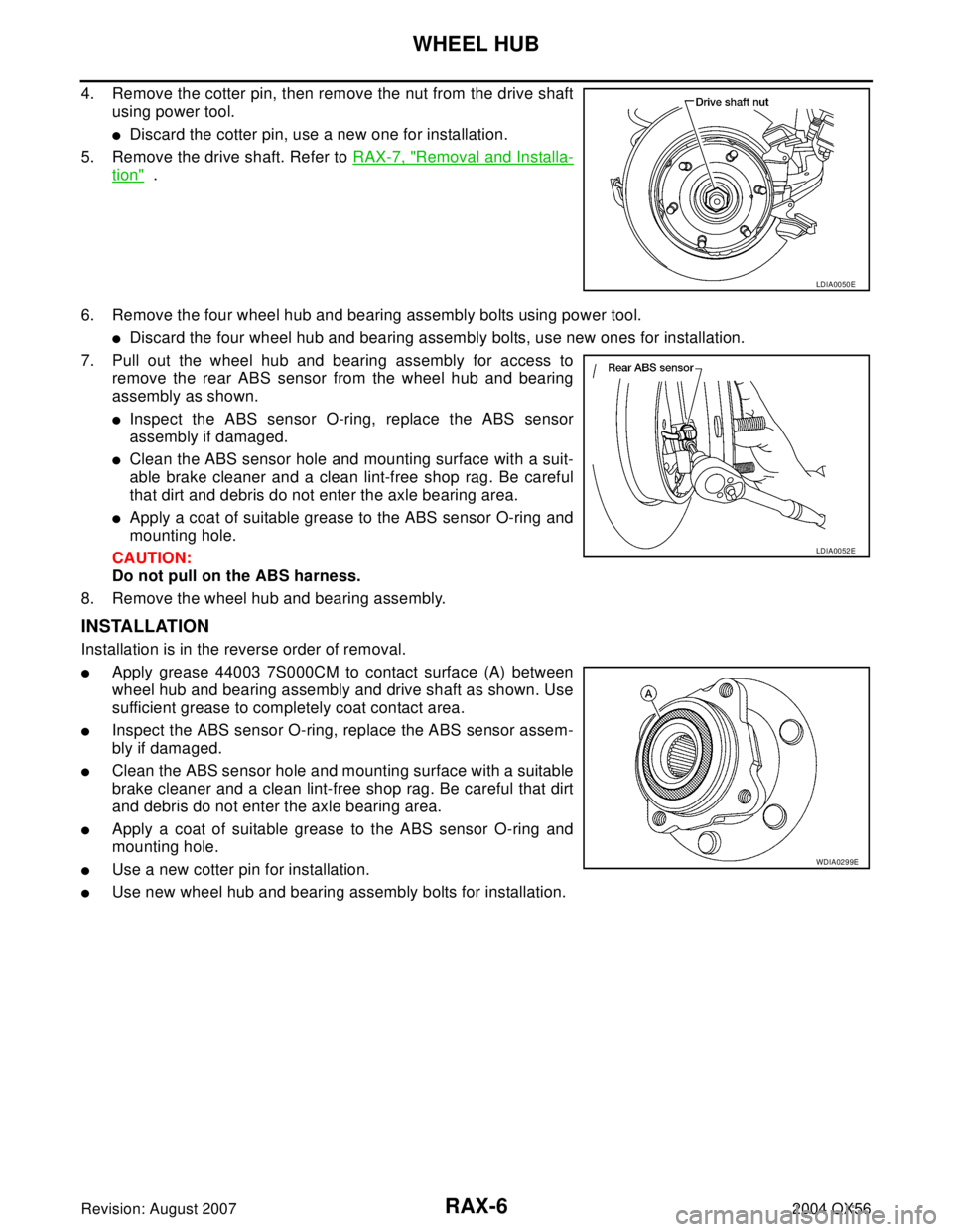
4. Remove the cotter pin, then remove the nut from the drive shaft
using power tool.
�Discard the cotter pin, use a new one for installation.
5. Remove the drive shaft. Refer to RAX-7, "
Removal and Installa-
tion" .
6. Remove the four wheel hub and bearing assembly bolts using power tool.
�Discard the four wheel hub and bearing assembly bolts, use new ones for installation.
7. Pull out the wheel hub and bearing assembly for access to
remove the rear ABS sensor from the wheel hub and bearing
assembly as shown.
�Inspect the ABS sensor O-ring, replace the ABS sensor
assembly if damaged.
�Clean the ABS sensor hole and mounting surface with a suit-
able brake cleaner and a clean lint-free shop rag. Be careful
that dirt and debris do not enter the axle bearing area.
�Apply a coat of suitable grease to the ABS sensor O-ring and
mounting hole.
CAUTION:
Do not pull on the ABS harness.
8. Remove the wheel hub and bearing assembly.
INSTALLATION
Installation is in the reverse order of removal.
�Apply grease 44003 7S000CM to contact surface (A) between
wheel hub and bearing assembly and drive shaft as shown. Use
sufficient grease to completely coat contact area.
�Inspect the ABS sensor O-ring, replace the ABS sensor assem-
bly if damaged.
�Clean the ABS sensor hole and mounting surface with a suitable
brake cleaner and a clean lint-free shop rag. Be careful that dirt
and debris do not enter the axle bearing area.
�Apply a coat of suitable grease to the ABS sensor O-ring and
mounting hole.
�Use a new cotter pin for installation.
�Use new wheel hub and bearing assembly bolts for installation.
LDIA0050E
LDIA0052E
WDIA0299E
Page 2794 of 3371
REAR DRIVE SHAFT
RAX-7
C
E
F
G
H
I
J
K
L
MA
B
RAX
Revision: August 20072004 QX56
REAR DRIVE SHAFTPFP:39600
ComponentsEDS0035D
Rear Drive Shaft
Removal and InstallationEDS0 01 AV
REMOVAL
1. Remove the wheel and tire using power tool.
2. Remove the stabilizer bar clamp. Refer to RSU-25, "
Components" .
3. Remove the cotter pin and discard, then remove the drive shaft
nut from the drive shaft.
�Do not reuse the cotter pin, discard after removal and use a
new cotter pin for installation.
4. Remove the six bolts from the inside flange of the drive shaft using power tool and discard the bolts.
�Do not reuse the drive shaft inside flange bolts, discard after removal and use new bolts for installation.
WDIA0301E
1. Rear final drive assembly 2. Rear drive shaft 3. Rear brake and hub assembly
4. Cotter pin⇐: Vehicle front
LDIA0050E
Page 2795 of 3371
RAX-8
REAR DRIVE SHAFT
Revision: August 20072004 QX56
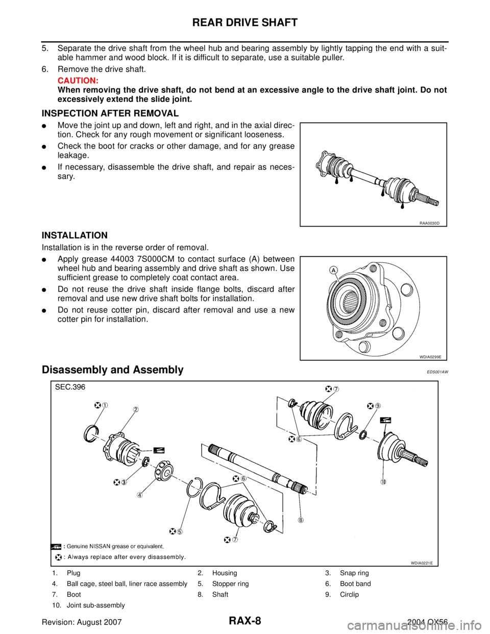
5. Separate the drive shaft from the wheel hub and bearing assembly by lightly tapping the end with a suit-
able hammer and wood block. If it is difficult to separate, use a suitable puller.
6. Remove the drive shaft.
CAUTION:
When removing the drive shaft, do not bend at an excessive angle to the drive shaft joint. Do not
excessively extend the slide joint.
INSPECTION AFTER REMOVAL
�Move the joint up and down, left and right, and in the axial direc-
tion. Check for any rough movement or significant looseness.
�Check the boot for cracks or other damage, and for any grease
leakage.
�If necessary, disassemble the drive shaft, and repair as neces-
sary.
INSTALLATION
Installation is in the reverse order of removal.
�Apply grease 44003 7S000CM to contact surface (A) between
wheel hub and bearing assembly and drive shaft as shown. Use
sufficient grease to completely coat contact area.
�Do not reuse the drive shaft inside flange bolts, discard after
removal and use new drive shaft bolts for installation.
�Do not reuse cotter pin, discard after removal and use a new
cotter pin for installation.
Disassembly and AssemblyEDS001AW
RAA0030D
WDIA0299E
1. Plug 2. Housing 3. Snap ring
4. Ball cage, steel ball, liner race assembly 5. Stopper ring 6. Boot band
7. Boot 8. Shaft 9. Circlip
10. Joint sub-assembly
WDIA0221E
Page 2886 of 3371
REAR SUSPENSION ASSEMBLY
RSU-27
C
D
F
G
H
I
J
K
L
MA
B
RSU
Revision: August 20072004 QX56
Wheel Alignment InspectionEES0011H
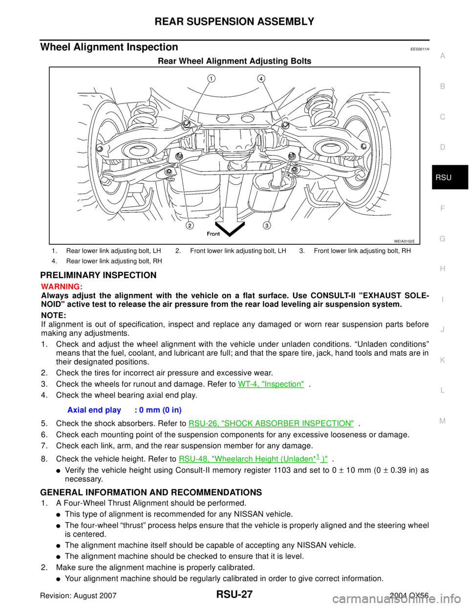
Rear Wheel Alignment Adjusting Bolts
PRELIMINARY INSPECTION
WA RN ING:
Always adjust the alignment with the vehicle on a flat surface. Use CONSULT-II "EXHAUST SOLE-
NOID" active test to release the air pressure from the rear load leveling air suspension system.
NOTE:
If alignment is out of specification, inspect and replace any damaged or worn rear suspension parts before
making any adjustments.
1. Check and adjust the wheel alignment with the vehicle under unladen conditions. “Unladen conditions”
means that the fuel, coolant, and lubricant are full; and that the spare tire, jack, hand tools and mats are in
their designated positions.
2. Check the tires for incorrect air pressure and excessive wear.
3. Check the wheels for runout and damage. Refer to WT-4, "
Inspection" .
4. Check the wheel bearing axial end play.
5. Check the shock absorbers. Refer to RSU-26, "
SHOCK ABSORBER INSPECTION" .
6. Check each mounting point of the suspension components for any excessive looseness or damage.
7. Check each link, arm, and the rear suspension member for any damage.
8. Check the vehicle height. Refer to RSU-48, "
Wheelarch Height (Unladen*1 )" .
�Verify the vehicle height using Consult-II memory register 1103 and set to 0 ± 10 mm (0 ± 0.39 in) as
necessary.
GENERAL INFORMATION AND RECOMMENDATIONS
1. A Four-Wheel Thrust Alignment should be performed.
�This type of alignment is recommended for any NISSAN vehicle.
�The four-wheel “thrust” process helps ensure that the vehicle is properly aligned and the steering wheel
is centered.
�The alignment machine itself should be capable of accepting any NISSAN vehicle.
�The alignment machine should be checked to ensure that it is level.
2. Make sure the alignment machine is properly calibrated.
�Your alignment machine should be regularly calibrated in order to give correct information.
WEIA0102E
1. Rear lower link adjusting bolt, LH 2. Front lower link adjusting bolt, LH 3. Front lower link adjusting bolt, RH
4. Rear lower link adjusting bolt, RH
Axial end play : 0 mm (0 in)