Page 1187 of 3371

DI-84
REAR VIEW MONITOR
Revision: August 20072004 QX56
Rear View Is Not Displayed With The A/T Selector Lever In R PositionEKS007RC
1. BACK-UP LAMP INSPECTION
1. Turn ignition switch ON.
2. Shift A/T selector lever to R position.
Does back-up lamp illuminate?
YES >> GO TO 2.
NO >> Check back-up lamp system. Refer to LT-106, "
BACK-UP LAMP" .
2. CHECK REVERSE POSITION INPUT SIGNAL
With CONSULT-II
Select “DATA MONITOR” of “REARVIEW CAMERA”. Operate igni-
tion switch with “R POSI SIG” of “DATA MONITOR” and check oper-
ate status.
Without CONSULT-II
1. Turn ignition switch OFF.
2. Disconnect rear view camera control unit connector.
3. Turn ignition switch ON.
4. Shift A/T selector lever to R position.
5. Check voltage between rear view camera control unit harness
connector B73 terminal 4 (G/W) and ground.
OK or NG
OK >> GO TO 3.
NG >> Check harness for open or short between rear view
camera control unit and back-up lamp relay.
3. CHECK DISPLAY CONTROL UNIT OUTPUT SIGNAL
1. Turn ignition switch OFF.
2. Disconnect rear view camera control unit connector.
3. Turn ignition switch ON.
4. Check voltage between rear view camera control unit harness
connector B73 terminal 5 (BR) and ground.
OK or NG
OK >> GO TO 5.
NG >> GO TO 4.
SKIA7147E
Battery voltage should exist.
SKIA5086E
Voltage : Approx. 5V
SKIA7148E
Page 1188 of 3371

REAR VIEW MONITOR
DI-85
C
D
E
F
G
H
I
J
L
MA
B
DI
Revision: August 20072004 QX56
4. CHECK DISPLAY CONTROL UNIT CIRCUIT
1. Turn ignition switch OFF.
2. Disconnect display control unit connector.
3. Check continuity between rear view camera control unit harness
connector B73 terminal 5 (BR) and display control unit harness
connector M94 terminal 8 (BR).
4. Check continuity between rear view camera control unit harness
connector B73 terminal 5 (BR) and ground.
OK or NG
OK >> Replace display control unit. Refer to AV-158, "Removal and Installation of Display Control Unit" .
NG >> Repair harness or connector.
5. CHECK AV CONTROL SIGNAL
1. Turn ignition switch OFF.
2. Connect rear view camera control unit connector.
3. Shift A/T selector lever to R position.
4. Check voltage between rear view camera control unit harness
connector B73 terminal 5 (BR) and ground.
OK or NG
OK >> GO TO 6.
NG >> Replace rear view camera control unit. Refer to DI-88,
"Removal and Installation of Rear View Camera Control
Unit" .
6. CHECK REAR VIEW CAMERA OPEN CIRCUIT
1. Turn ignition switch OFF.
2. Disconnect rear view camera connector.
3. Check continuity between rear view camera control unit harness
connector B73 terminal 8 (Y) and rear view camera harness
connector D504 terminal 1 (Y).
4. Check continuity between rear view camera control unit harness
connector B73 terminal 9 and rear view camera harness con-
nector D504 terminal 4.
5. Check continuity between rear view camera control unit harness connector B73 terminal 10 (G) and rear
view camera harness connector D504 terminal 3 (G).
OK or NG
OK >> GO TO 7.
NG >> Repair harness or connector.Continuity should exist.
Continuity should not exist.
SKIA7149E
Voltage : Approx. 0V
SKIA7150E
Continuity should exist.
Continuity should exist.
Continuity should exist.
SKIA5095E
Page 1190 of 3371

REAR VIEW MONITOR
DI-87
C
D
E
F
G
H
I
J
L
MA
B
DI
Revision: August 20072004 QX56
10. CHECK REAR VIEW CAMERA SIGNAL
1. Connect rear view camera connector.
2. Turn ignition switch ON.
3. Shift A/T selector lever to R position.
4. Check voltage signal between rear view camera control unit har-
ness connector B73 terminal 10 (G) and ground.
OK or NG
OK >> GO TO 11.
NG >> Replace the rear view camera. Refer to DI-88, "
Removal and Installation of Rear View Camera" .
11 . CHECK COMPOSITE SIGNAL OPEN OR SHORT CIRCUIT
1. Turn ignition switch OFF.
2. Disconnect rear view camera control unit connector and display
unit connector.
3. Check continuity between rear view camera control unit harness
connector B73 terminal 12 (W) and display unit harness connec-
tor M93 terminal 15 (W).
4. Check continuity between rear view camera control unit harness
connector B73 terminal 12 (W) and ground.
OK or NG
OK >> GO TO 12.
NG >> Repair harness or connector.
12. CHECK COMPOSITE SIGNAL GROUND CIRCUIT
1. Check continuity between rear view camera control unit harness
connector B73 terminal 11 and display unit harness connector
M93 terminal 4.
2. Check continuity between rear view camera control unit harness
connector B73 terminal 11 and ground.
OK or NG
OK >> GO TO 13.
NG >> Repair harness or connector.10 (G) - Ground:
SKIA5100E
SKIA4894E
Continuity should exist.
Continuity should not exist.
WKIA1825E
Continuity should exist.
Continuity should not exist.
WKIA1826E
Page 1191 of 3371

DI-88
REAR VIEW MONITOR
Revision: August 20072004 QX56
13. CHECK REAR VIEW CAMERA CONTROL UNIT COMPOSITE SIGNAL
1. Connect rear view camera control unit connector and display
unit connector.
2. Turn ignition switch ON.
3. Check voltage signal between rear view camera control unit har-
ness connector B73 terminal 12 (W) and ground.
OK or NG
OK >> Replace the display unit. Refer to AV- 1 5 8 , "Removal and Installation of Display Unit" .
NG >> Replace the rear view camera control unit. Refer to DI-88, "
Removal and Installation of Rear View
Camera Control Unit" .
Removal and Installation of Rear View Camera Control UnitEKS007RE
REMOVAL
1. Remove luggage side finisher lower LH. Refer to EI-39, "LUG-
GAGE FLOOR TRIM" .
2. Remove screws (2), and remove rear view camera control unit.
INSTALLATION
Installation is in the reverse order of removal.
Removal and Installation of Rear View CameraEKS007RF
REMOVAL
1. Remove back door lower finisher. Refer to EI-41, "BACK DOOR TRIM" .
2. Remove connector.
3. Remove screws (2), and remove rear view camera.
INSTALLATION
Installation is in the reverse order of removal.12 (W) - Ground:
WKIA1827E
SKIA4896E
LKIA0478E
LKIA0479E
Page 1199 of 3371

EC-8Revision: August 2007
INDEX FOR DTC
2004 QX56
INDEX FOR DTCPFP:00024
Alphabetical IndexUBS00GZ3
NOTE:
If DTC U1000 or U1001 is displayed with other DTC, first perform the trouble diagnosis for DTC U1000,
U1001. Refer to EC-135, "
DTC U1000, U1001 CAN COMMUNICATION LINE" .
×:Applicable —: Not applicable
Items
(CONSULT-II screen terms)DTC*
1
TripMIL lighting
upReference page
CONSULT-II
GST*
2ECM*3
A/F SEN1 (B1) P1271 1271 2×EC-429
A/F SEN1 (B1) P1272 1272 2×EC-437
A/F SEN1 (B1) P1273 1273 2×EC-445
A/F SEN1 (B1) P1274 1274 2×EC-454
A/F SEN1 (B1) P1276 1276 2×EC-463
A/F SEN1 (B1) P1278 1278 2×EC-472
A/F SEN1 (B1) P1279 1279 2×EC-484
A/F SEN1 (B2) P1281 1281 2×EC-429
A/F SEN1 (B2) P1282 1282 2×EC-437
A/F SEN1 (B2) P1283 1283 2×EC-445
A/F SEN1 (B2) P1284 1284 2×EC-454
A/F SEN1 (B2) P1286 1286 2×EC-463
A/F SEN1 (B2) P1288 1288 2×EC-472
A/F SEN1 (B2) P1289 1289 2×EC-484
A/F SEN1 HTR (B1) P1031 1031 2×EC-354
A/F SEN1 HTR (B1) P1032 1032 2×EC-354
A/F SEN1 HTR (B2) P1051 1051 2×EC-354
A/F SEN1 HTR (B2) P1052 1052 2×EC-354
ACC COMMAND VALUE*7P1568 1568 1 —EC-524
A/T INTERLOCK P1730 1730 1×AT-139
A/T TCC S/V FNCTN P0744 0744 2×AT-121
APP SEN 1/CIRC P2122 2122 1×EC-556
APP SEN 1/CIRC P2123 2123 1×EC-556
APP SEN 2/CIRC P2127 2127 1×EC-562
APP SEN 2/CIRC P2128 2128 1×EC-562
APP SENSOR P2138 2138 1×EC-576
ASCD BRAKE SW P1572 1572 1 —EC-525, EC-534
ASCD SW P1564 1564 1 —EC-510, EC-517
ASCD VHL SPD SEN*6P1574 1574 1 —EC-542, EC-544
ATF TEMP SEN/CIRC P0710 0710 2×AT-131
BRAKE SW/CIRCUIT P1805 1805 2 —EC-551
CAN COMM CIRCUIT U1000
1000*41×EC-135
CAN COMM CIRCUIT U1001
1001*42—EC-135
CKP SEN/CIRCUIT P0335 0335 2×EC-255
CLOSED LOOP-B1 P1148 1148 1×EC-407
CLOSED LOOP-B2 P1168 1168 1×EC-407
Page 1203 of 3371

EC-12Revision: August 2007
INDEX FOR DTC
2004 QX56
DTC No. IndexUBS00GZ4
NOTE:
If DTC U1000 or U1001 is displayed with other DTC, first perform the trouble diagnosis for DTC U1000,
U1001. Refer to EC-135, "
DTC U1000, U1001 CAN COMMUNICATION LINE" .
×:Applicable —: Not applicable
DTC*
1
Items
(CONSULT-II screen terms)TripMIL lighting
upReference page
CONSULT-II
GST*
2ECM*3
U1000
1000*4CAN COMM CIRCUIT 1×EC-135
U1001
1001*4CAN COMM CIRCUIT 2 —EC-135
P0000 0000NO DTC IS DETECTED.
FURTHER TESTING
MAY BE REQUIRED.———
P0037 0037 HO2S2 HTR (B1) 2×EC-138
P0038 0038 HO2S2 HTR (B1) 2×EC-138
P0057 0057 HO2S2 HTR (B2) 2×EC-138
P0058 0058 HO2S2 HTR (B2) 2×EC-138
P0101 0101 MAF SEN/CIRCUIT 1×EC-146
P0102 0102 MAF SEN/CIRCUIT 1×EC-154
P0103 0103 MAF SEN/CIRCUIT 1×EC-154
P 0 11 2 0 11 2 I AT S E N /C I R C U I T 2×EC-161
P 0 11 3 0 11 3 I AT S E N /C I R C U I T 2×EC-161
P0117 0117 ECT SEN/CIRCUIT 1×EC-165
P0118 0118 ECT SEN/CIRCUIT 1×EC-165
P0122 0122 TP SEN 2/CIRC 1×EC-171
P0123 0123 TP SEN 2/CIRC 1×EC-171
P0125 0125 ECT SENSOR 1×EC-178
P0127 0127 IAT SENSOR 2×EC-181
P0128 0128 THERMSTAT FNCTN 2×EC-184
P0138 0138 HO2S2 (B1) 2×EC-186
P0139 0139 HO2S2 (B1) 2×EC-196
P0158 0158 HO2S2 (B2) 2×EC-186
P0159 0159 HO2S2 (B2) 2×EC-196
P0171 0171 FUEL SYS-LEAN-B1 2×EC-208
P0172 0172 FUEL SYS-RICH-B1 2×EC-217
P0174 0174 FUEL SYS-LEAN-B2 2×EC-208
P0175 0175 FUEL SYS-RICH-B2 2×EC-217
P0181 0181 FTT SENSOR 2×EC-225
P0182 0182 FTT SEN/CIRCUIT 2×EC-231
P0183 0183 FTT SEN/CIRCUIT 2×EC-231
P0222 0222 TP SEN 1/CIRC 1×EC-236
P0223 0223 TP SEN 1/CIRC 1×EC-236
P0300 0300 MULTI CYL MISFIRE 2×EC-243
P0301 0301 CYL 1 MISFIRE 2×EC-243
P0302 0302 CYL 2 MISFIRE 2×EC-243
P0303 0303 CYL 3 MISFIRE 2×EC-243
Page 1209 of 3371
EC-18Revision: August 2007
PRECAUTIONS
2004 QX56
�After performing each TROUBLE DIAGNOSIS, perform DTC
Confirmation Procedure or Overall Function Check.
The DTC should not be displayed in the DTC Confirmation
Procedure if the repair is completed. The Overall Function
Check should be a good result if the repair is completed.
�When measuring ECM signals with a circuit tester, never
allow the two tester probes to contact.
Accidental contact of probes will cause a short circuit and
damage the ECM power transistor.
�Do not use ECM ground terminals when measuring input/
output voltage. Doing so may result in damage to the ECM's
transistor. Use a ground other than ECM terminals, such as
the ground.
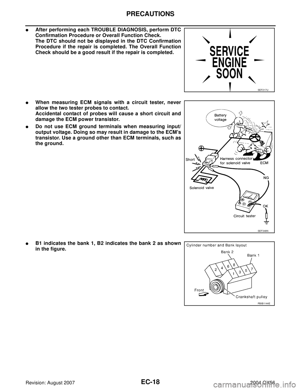
�B1 indicates the bank 1, B2 indicates the bank 2 as shown
in the figure.
SEF 2 17 U
SEF 3 48 N
PBIB11 44 E
Page 1226 of 3371

BASIC SERVICE PROCEDURE
EC-35
C
D
E
F
G
H
I
J
K
L
MA
EC
Revision: August 20072004 QX56
INSPECTION PROCEDURE
1. INSPECTION START
1. Check service records for any recent repairs that may indicate a related malfunction, or a current need for
scheduled maintenance.
2. Open engine hood and check the following:
–Harness connectors for improper connections
–Wiring harness for improper connections, pinches and cut
–Vacuum hoses for splits, kinks and improper connections
–Hoses and ducts for leaks
–Air cleaner clogging
–Gasket
3. Confirm that electrical or mechanical loads are not applied.
–Headlamp switch is OFF.
–Air conditioner switch is OFF.
–Rear window defogger switch is OFF.
–Steering wheel is in the straight-ahead position, etc.
4. Start engine and warm it up until engine coolant temperature
indicator points the middle of gauge.
Ensure engine stays below 1,000 rpm.
5. Run engine at about 2,000 rpm for about 2 minutes under no
load.
6. Make sure that no DTC is displayed with CONSULT-II or GST.
OK or NG
OK >> GO TO 3.
NG >> GO TO 2.
2. REPAIR OR REPLACE
Repair or replace components as necessary according to corresponding Diagnostic Procedure.
>> GO TO 3.
SEF 9 83 U
SEF 9 76 U
SEF 9 77 U