Page 3169 of 3371

TF-44
TROUBLE DIAGNOSIS — INTRODUCTION
Revision: August 20072004 QX56
TROUBLE DIAGNOSIS — INTRODUCTIONPFP:00000
IntroductionEDS0017W
DESCRIPTION
When a malfunction (indicated by the 4WD warning lamp illumination) occurs, collect information first from the
customer about how the malfunction occurs. Then, proceed with the diagnosis presuming it is the cause. Also
inspect the electrical system, paying close attention to other possibilities such as fluid level and leaks.
All-mode 4WD transfer is controlled by transfer control unit and sensors.
If a malfunction occurs in the all-mode 4WD system, the 4WD warning lamp lights up to inform of the system
malfunction. There are two ways to identify the cause of the malfunction.
1. Performing the self-diagnosis. (The 4WD warning lamp will indicate what kind of malfunction has occurred
by flickering.)
2. Performing diagnosis using CONSULT-II.
DIAGNOSTIC WORKSHEET
Information from Customer
KEY POINTS
�WHAT ..... Vehicle model
�WHEN..... Date, Frequencies
�WHERE..... Road conditions
�HOW..... Operating conditions, Symptoms
Diagnostic Worksheet
Information sheet from customer
Customer name MR/MS Model & Year VIN
Transfer model
AT X 1 4 BEngine Mileage
Incident Date Manuf. Date In Service Date
Frequency❏ Continuous ❏ Intermittent ( times a day)
Symptoms❏ 4WD shift indicator lamp does not turn on.
❏ 4WD warning lamp does not turn on.
❏ 4WD shift indicator lamp does not turn off.
❏ ATP warning lamp does not turn on.
❏ 4LO indicator lamp does not turn on.
❏ 4WD shift indicator lamp does not indicate “4H”.
❏ 4WD shift indicator lamp repeats flicking.
❏ Tight corner braking symptom occurs.
❏ 4WD system does not operate.
❏ Others.
4WD warning lamp❏ Continuously lit❏ Not lit
1.❏ Listen to customer complaints.TF-47
2.❏ Check transfer fluid.TF-47
❏ Leakage
❏ Fluid condition
❏ Fluid level
3.❏ Road testingTF-47
❏ 1. Check before engine is started.
❏ 2. Check at idle.
❏ 3. Cruise test
4.❏ Perform self-diagnosis NG items (with CONSULT-II and without CONSULT-II).TF-31
, TF-28
Page 3172 of 3371

TROUBLE DIAGNOSIS — BASIC INSPECTION
TF-47
C
E
F
G
H
I
J
K
L
MA
B
TF
Revision: August 20072004 QX56
TROUBLE DIAGNOSIS — BASIC INSPECTIONPFP:00000
Listen to Customer ComplaintsEDS0017Y
�Each customer feels differently about a problem. It is important to fully understand the symptoms or condi-
tions for a customer complaint.
�Listen to the customer about how and when the malfunction occurs, and make good use of it when per-
forming the road test.
Transfer Fluid CheckEDS0017Z
�Check fluid for leaks and fluid level. Refer to TF-47, "Transfer Fluid Check" .
Road TestEDS00180
PREPARATION FOR ROAD TEST
�The purpose of the test is to determine overall performance of
transfer and analyze causes of problems.
�When a malfunction is found in any part of transfer, perform the
road test to locate the malfunction area and repair the malfunc-
tion parts.
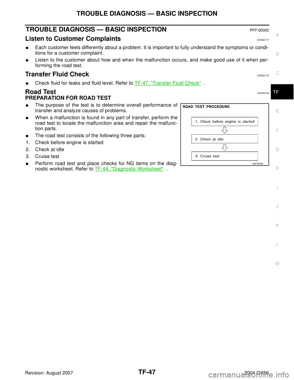
�The road test consists of the following three parts:
1. Check before engine is started
2. Check at idle
3. Cruise test
�Perform road test and place checks for NG items on the diag-
nostic worksheet. Refer to TF-44, "
Diagnostic Worksheet" .
SMT089D
Page 3178 of 3371

TROUBLE DIAGNOSIS — BASIC INSPECTION
TF-53
C
E
F
G
H
I
J
K
L
MA
B
TF
Revision: August 20072004 QX56
3. CRUISE TEST
1. INSPECTION START
Do you have CONSULT-II?
Ye s o r N o
Yes >> GO TO 2.
No >> GO TO 3.
2. CHECK INPUT SIGNAL
With CONSULT-II
1. Warm up engine to normal operating temperature.
2. Park vehicle on flat surface.
3. Set 4WD shift switch to 4H position.
4. Set 4WD shift switch to AUTOposition.
5. Start engine.
6. Drive for at least 30 seconds at a speed higher than 20 km/h (12 MPH).
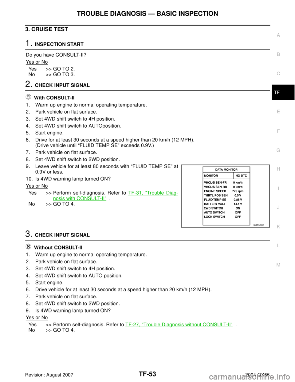
(Drive vehicle until “FLUID TEMP SE” exceeds 0.9V.)
7. Park vehicle on flat surface.
8. Set 4WD shift switch to 2WD position.
9. Leave vehicle for at least 80 seconds with “FLUID TEMP SE” at
0.9V or less.
10. Is 4WD warning lamp turned ON?
Ye s o r N o
Yes >> Perform self-diagnosis. Refer to TF-31, "Trouble Diag-
nosis with CONSULT-II" .
No >> GO TO 4.
3. CHECK INPUT SIGNAL
Without CONSULT-II
1. Warm up engine to normal operating temperature.
2. Park vehicle on flat surface.
3. Set 4WD shift switch to 4H position.
4. Set 4WD shift switch to AUTO position.
5. Start engine.
6. Drive vehicle for at least 30 seconds at a speed higher than 20 km/h (12 MPH).
7. Park vehicle on flat surface.
8. Set 4WD shift switch to 2WD position.
9. Is 4WD warning lamp turned ON?
Ye s o r N o
Yes >> Perform self-diagnosis. Refer to TF-27, "Trouble Diagnosis without CONSULT-II" .
No >> GO TO 4.
SMT972D
Page 3182 of 3371

TROUBLE DIAGNOSIS — GENERAL DESCRIPTION
TF-57
C
E
F
G
H
I
J
K
L
MA
B
TF
Revision: August 20072004 QX56
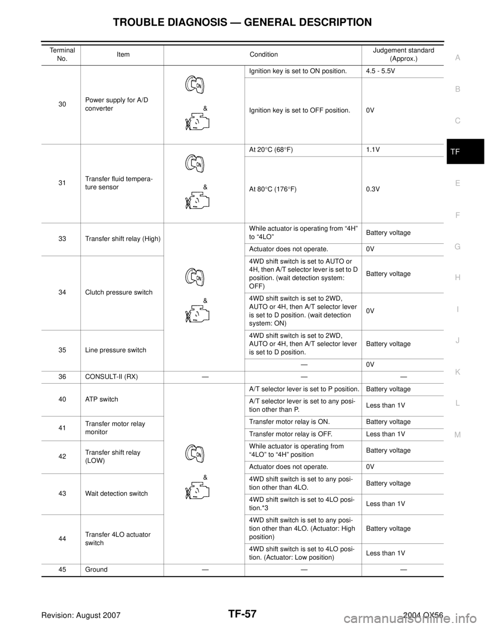
30Power supply for A/D
converter &Ignition key is set to ON position. 4.5 - 5.5V
Ignition key is set to OFF position. 0V
31Transfer fluid tempera-
ture sensor &At 20°C (68°F) 1.1V
At 80°C (176°F) 0.3V
33 Transfer shift relay (High)
&While actuator is operating from “4H”
to “4LO”Battery voltage
Actuator does not operate. 0V
34 Clutch pressure switch4WD shift switch is set to AUTO or
4H, then A/T selector lever is set to D
position. (wait detection system:
OFF)Battery voltage
4WD shift switch is set to 2WD,
AUTO or 4H, then A/T selector lever
is set to D position. (wait detection
system: ON)0V
35 Line pressure switch4WD shift switch is set to 2WD,
AUTO or 4H, then A/T selector lever
is set to D position.Battery voltage
—0V
36 CONSULT-II (RX) — — —
40 ATP switch
&A/T selector lever is set to P position. Battery voltage
A/T selector lever is set to any posi-
tion other than P.Less than 1V
41Transfer motor relay
monitorTransfer motor relay is ON. Battery voltage
Transfer motor relay is OFF. Less than 1V
42Transfer shift relay
(LOW)While actuator is operating from
“4LO” to “4H” positionBattery voltage
Actuator does not operate. 0V
43 Wait detection switch4WD shift switch is set to any posi-
tion other than 4LO.Battery voltage
4WD shift switch is set to 4LO posi-
tion.*3Less than 1V
44Transfer 4LO actuator
switch4WD shift switch is set to any posi-
tion other than 4LO. (Actuator: High
position)Battery voltage
4WD shift switch is set to 4LO posi-
tion. (Actuator: Low position)Less than 1V
45 Ground — — — Te r m i n a l
No.Item ConditionJudgement standard
(Approx.)
Page 3187 of 3371
TF-62
2-4WD SHIFT SOLENOID VALVE AND 4WD SHIFT SWITCH
Revision: August 20072004 QX56
2-4WD SHIFT SOLENOID VALVE AND 4WD SHIFT SWITCHPFP:00000
Diagnostic ProcedureEDS00184
1. CHECK 2-4WD SHIFT SOLENOID VALVE AND 4WD SHIFT SWITCH
Refer to TF-95, "
2-4WD SHIFT SOLENOID VALVE AND TRANS-
FER FLUID TEMPERATURE SENSOR" and TF-95, "4WD SHIFT
SWITCH" .
OK or NG
OK >> GO TO 2.
NG >> Repair or replace 2-4WD shift solenoid valve or 4WD
shift switch.
2. CHECK INPUT SIGNAL
With CONSULT-II
1. Select “ECU INPUT SIGNALS” in Data Monitor.
2. Read out ON/OFF status of “2WD SW” and “LOCK SWITCH”.
OK or NG
OK >> 1. Perform transfer control unit input/output signal
inspection. Refer to TF-55, "
TRANSFER CONTROL
UNIT INSPECTION TABLE" .
2. If NG, recheck transfer control unit pin terminals for
damage or loose connection with harness connector.
NG >> GO TO 3.
SMT778D
SMT974D
Page 3191 of 3371
TF-66
TRANSFER FLUID TEMPERATURE SENSOR
Revision: August 20072004 QX56
TRANSFER FLUID TEMPERATURE SENSORPFP:00000
Diagnostic ProcedureEDS00186
1. CHECK TRANSFER FLUID TEMPERATURE SENSOR
Refer to TF-95, "
2-4WD SHIFT SOLENOID VALVE AND TRANSFER FLUID TEMPERATURE SENSOR" .
OK or NG
OK >> GO TO 2.
NG >> Repair or replace fluid temperature sensor.
2. CHECK INPUT SIGNAL
Do you have CONSULT-II?
Ye s o r N o
Yes >> GO TO 3.
No >> GO TO 4.
Page 3192 of 3371
TRANSFER FLUID TEMPERATURE SENSOR
TF-67
C
E
F
G
H
I
J
K
L
MA
B
TF
Revision: August 20072004 QX56
3. CHECK INPUT SIGNAL
With CONSULT-II
1. Start engine.
2. Select “ECU INPUT SIGNALS” in Data Monitor.
3. Read out the value of “FLUID TEMP SE”.
OK or NG
OK >> GO TO 5.
NG >> Check the following.
�Continuity between transfer control unit and transfer terminal cord assembly harness connectorVo l ta g e
20°C (68°F) : Approx. 1.1V
80°C (176°F) : Approx. 0.3V
SMT784D
SMT974D
Page 3193 of 3371
TF-68
TRANSFER FLUID TEMPERATURE SENSOR
Revision: August 20072004 QX56
4. CHECK INPUT SIGNAL
Without CONSULT-II
1. Turn ignition switch to ON position.
2. Check voltage between transfer control unit harness connector
E143 terminals 28 (B/G) and 31(G).
OK or NG
OK >> GO TO 5.
NG >> Check the following.
�Continuity between transfer control unit and transfer
terminal cord assembly harness connector
5. PERFORM SELF-DIAGNOSIS AGAIN
After driving for a while, perform self-diagnosis again.
Refer to TF-27, "
Trouble Diagnosis without CONSULT-II" .
OK or NG
OK >> Inspection End.
NG >> 1. Perform transfer control unit input/output signal inspection. Refer to TF-55, "
TRANSFER CON-
TROL UNIT INSPECTION TABLE" .
2. If NG, recheck transfer control unit pin terminals for damage or loose connection with harness
connector.Vo l ta g e
20°C (68°F) : Approx. 1.1V
80°C (176°F) : Approx. 0.3V
LDIA0072E