Page 3219 of 3371

EDS0018M
1. CHECK INPUT S")
TF-94
TROUBLE DIAGNOSES FOR SYMPTOMS
Revision: August 20072004 QX56
Symptom 9. 4WD System Does Not Operate (The Vehicle Cannot Be Put Into
4WD Mode-Hydraulic System Failure)
EDS0018M
1. CHECK INPUT SIGNAL
With CONSULT-II
1. Select “ECU INPUT SIGNALS” in Data Monitor.
2. Put A/T selector lever in D.
3. Turn 4WD shift switch to 4H and back to 2WD while reading out
ON/OFF status of "CL PRES SW".
Without CONSULT-II
Check voltage between transfer control unit harness connector E143
terminal 34 (BR) and ground.
Refer to TF-55, "
TRANSFER CONTROL UNIT INSPECTION
TABLE" .
OK or NG
OK >> 1. Check transfer fluid level.
2. Disassemble transfer unit and check the following.
–Transfer motor
–Main oil pump assembly
–Sub-oil pump assembly
–Oil strainer
–Control valve assembly
–2-4WD shift solenoid valve
–Oil filter element
–Lip seal
–Strainer O-ring
–Main oil pump drive gear
–Seal ring
–D-ring
–Clutch piston
–Clutch assembly
NG >> GO TO 2.
2. CHECK CLUTCH PRESSURE CIRCUIT
Check clutch pressure switch circuit.
Refer to TF-72, "
Diagnostic Procedure" .
OK or NG
OK >> GO TO 3.
NG >> Check, repair or replace faulty parts.
3. CHECK PROCEDURES FROM THE BEGINNING
Check again.
OK or NG
OK >> Inspection End.
NG >> Recheck each connector pin terminals for damage or loose connection.
WDIA0087E
Page 3220 of 3371

TROUBLE DIAGNOSES FOR SYMPTOMS
TF-95
C
E
F
G
H
I
J
K
L
MA
B
TF
Revision: August 20072004 QX56
Component InspectionEDS0018N
4WD SHIFT SWITCH
Check continuity between each terminal.
2-4WD SHIFT SOLENOID VALVE AND TRANSFER FLUID TEMPERATURE SENSOR
Measure resistance between terminals of transfer terminal cord
assembly harness connector F56.
4WD SOLENOID VALVE, CLUTCH PRESSURE SWITCH AND LINE PRESSURE SWITCH
Measure resistance between terminals of transfer terminal cord
assembly harness connector F56.
Terminals Switch position Continuity
1 - 22WD Yes
Except 2WD No
1 - 3, 1 - 4AUTO Yes
Except AUTO No
1 - 4, 1 - 54H Yes
Except 4H No
1 - 4, 1 - 64LO Yes
Except 4LO No
WDIA0090E
Component parts TerminalsResistance
(Approx.)
2-4WD shift solenoid valve 4 - 520°C (68°F):
22.8 - 25.2Ω
Transfer fluid temperature
sensor2 - 320°C (68°F): 2.5 kΩ
80°C (176°F): 0.3 kΩ
LDIA0093E
Component
partsTerminals Remarks
4WD sole-
noid valve6
Ground
terminalApprox. 20°C (68°F): Approx. 3.0 - 3.4Ω
Clutch pres-
sure switch7In room temperature
�2-4WD shift solenoid valve “OFF”: No conti-
nuity
�2-4WD shift solenoid valve and transfer
motor “ON”: Continuity exists
Line pressure
switch1In room temperature
�Turn ignition switch to “OFF” position and
leave vehicle for more than 5 minutes.
(OFF): No continuity
�Transfer motor “ON”: Continuity exists
LDIA0094E
Page 3224 of 3371
FRONT OIL SEAL
TF-99
C
E
F
G
H
I
J
K
L
MA
B
TF
Revision: August 20072004 QX56
FRONT OIL SEALPFP:38189
Removal and InstallationEDS00315
REMOVAL
1. Partially drain the transfer fluid. Refer to MA-24, "Changing Transfer Fluid" .
2. Remove the front propeller shaft. Refer to PR-4, "
Removal and Installation" .
3. Remove the companion flange self-lock nut, using Tool.
4. Put a matching mark on top of the front drive shaft in line with
the mark on the companion flange.
CAUTION:
Use paint to make the matching mark on the front drive
shaft. Do not damage the front drive shaft.
5. Remove the companion flange, using suitable tool.
6. Remove the oil seal from the front case, using Tool.
CAUTION:
Do not damage front case.Tool number : KV40104000 ( — )
SDIA2657E
SDIA2658E
WDIA0193E
Tool number : ST33290001 (J-34286)
LDIA0144E
Page 3225 of 3371
TF-100
FRONT OIL SEAL
Revision: August 20072004 QX56
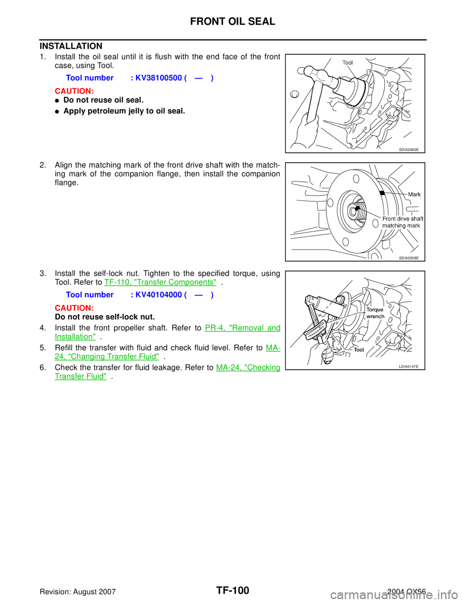
INSTALLATION
1. Install the oil seal until it is flush with the end face of the front
case, using Tool.
CAUTION:
�Do not reuse oil seal.
�Apply petroleum jelly to oil seal.
2. Align the matching mark of the front drive shaft with the match-
ing mark of the companion flange, then install the companion
flange.
3. Install the self-lock nut. Tighten to the specified torque, using
Tool. Refer to TF-110, "
Transfer Components" .
CAUTION:
Do not reuse self-lock nut.
4. Install the front propeller shaft. Refer to PR-4, "
Removal and
Installation" .
5. Refill the transfer with fluid and check fluid level. Refer to MA-
24, "Changing Transfer Fluid" .
6. Check the transfer for fluid leakage. Refer to MA-24, "
Checking
Transfer Fluid" . Tool number : KV38100500 ( — )
SDIA2662E
SDIA2658E
Tool number : KV40104000 ( — )
LDIA0147E
Page 3226 of 3371

REAR OIL SEAL
TF-101
C
E
F
G
H
I
J
K
L
MA
B
TF
Revision: August 20072004 QX56
REAR OIL SEALPFP:33140
Removal and InstallationEDS00316
REMOVAL
1. Partially drain the transfer fluid. Refer to MA-24, "Changing Transfer Fluid" .
2. Remove the rear propeller shaft. Refer to PR-8, "
Removal and Installation" .
3. Remove the dust cover from the rear case.
CAUTION:
Do not damage the rear case.
4. Remove the rear oil seal from the rear case, using Tool.
CAUTION:
Do not damage the rear case.
INSTALLATION
1. Install the oil seal until it is flush with the end face of the rear
case, using Tool.
CAUTION:
�Do not reuse oil seal.
�Apply petroleum jelly to oil seal.
2. Apply petroleum jelly to the circumference of the new dust cover.
Position the dust cover using the identification mark as shown.
CAUTION:
�Do not reuse dust cover.
�Position the identification mark at the position shown.
WDIA0127E
Tool number : ST33290001 (J-34286)
LDIA0139E
Tool number : ST30720000 (J-25405)
LDIA0140E
SDIA2208E
Page 3227 of 3371
TF-102
REAR OIL SEAL
Revision: August 20072004 QX56
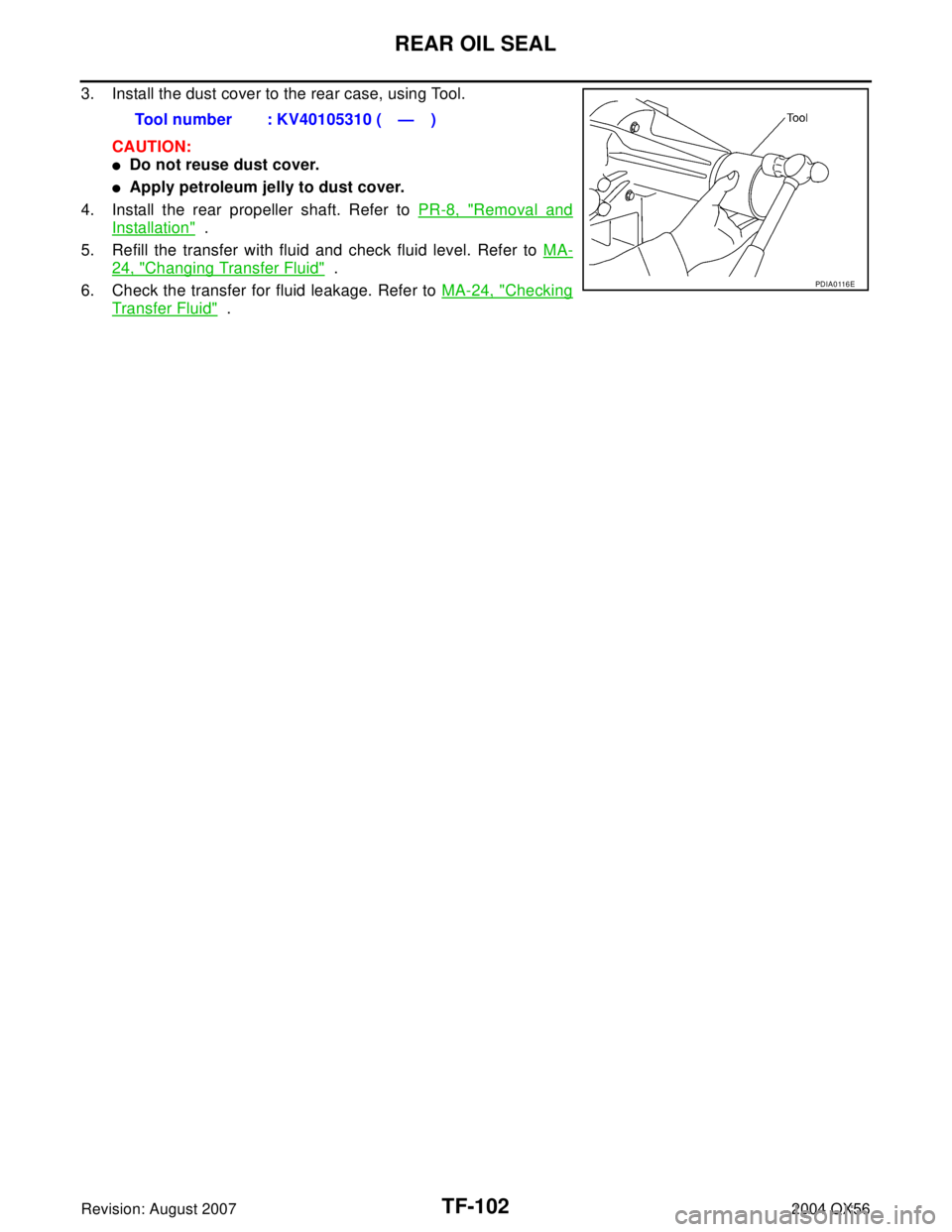
3. Install the dust cover to the rear case, using Tool.
CAUTION:
�Do not reuse dust cover.
�Apply petroleum jelly to dust cover.
4. Install the rear propeller shaft. Refer to PR-8, "
Removal and
Installation" .
5. Refill the transfer with fluid and check fluid level. Refer to MA-
24, "Changing Transfer Fluid" .
6. Check the transfer for fluid leakage. Refer to MA-24, "
Checking
Transfer Fluid" . Tool number : KV40105310 ( — )
PDIA0 116 E
Page 3233 of 3371
TF-108
TRANSFER OIL FILTER
Revision: August 20072004 QX56
3. Apply ATF to the two new O-rings (1), and install them on the oil
filter (2).
CAUTION:
Do not reuse O-rings.
4. Install the oil filter to the transfer assembly. Tighten the bolts to
the specified torque. Refer to TF-110, "
Transfer Components" .
CAUTION:
�Do not damage oil filter.
�Attach oil filter and tighten bolts evenly.
5. Check the transfer fluid. Refer to MA-24, "
Checking Transfer
Fluid" .
6. Start the engine for one minute. Then stop the engine and
recheck the transfer fluid.
WDIA0285E
SDIA2136E
Page 3245 of 3371
TF-120
CENTER CASE
Revision: August 20072004 QX56
3. Remove control valve assembly bolts.
4. Remove snap ring. Then push connector assembly into center
case to remove control valve assembly.
5. Remove lip seals from center case.
CAUTION:
There are two kinds of lip seals (lip seal of large inner diam-
eter: 5 pieces, lip seal of small inner diameter: 2 pieces).
Confirm the position before disassembly.
6. Remove all bolts except for the two as shown.
7. Remove 4WD solenoid valve, clutch pressure switch, 2-4WD
shift solenoid valve, line pressure switch, and transfer fluid tem-
perature sensor from control valve assembly.
SDIA2121E
SDIA2122E
SDIA2123E
SDIA2124E
PDIA0183E

, and install them on the oil
filter (2).
CAUTION:
Do not reuse O-rings.
4. Install the oil filter to t")
