Page 2468 of 3371
HEADLAMP (FOR CANADA) - DAYTIME LIGHT SYSTEM -
LT-37
C
D
E
F
G
H
I
J
L
MA
B
LT
Revision: August 20072004 QX56
Wiring Diagram — DTRL —EKS007AE
WKWA3110E
Page 2469 of 3371
LT-38
HEADLAMP (FOR CANADA) - DAYTIME LIGHT SYSTEM -
Revision: August 20072004 QX56
WKWA3111E
Page 2470 of 3371
HEADLAMP (FOR CANADA) - DAYTIME LIGHT SYSTEM -
LT-39
C
D
E
F
G
H
I
J
L
MA
B
LT
Revision: August 20072004 QX56
WKWA1402E
Page 2471 of 3371
LT-40
HEADLAMP (FOR CANADA) - DAYTIME LIGHT SYSTEM -
Revision: August 20072004 QX56
WKWA1403E
Page 2472 of 3371
HEADLAMP (FOR CANADA) - DAYTIME LIGHT SYSTEM -
LT-41
C
D
E
F
G
H
I
J
L
MA
B
LT
Revision: August 20072004 QX56
Terminals and Reference Values for BCMEKS007AF
Te r m i n a l
No.Wire
colorSignal nameMeasuring condition
Reference value
(Approx.) Ignition
switchOperation or condition
2 SB Combination switch input 5 ONLighting, turn, wiper OFF
Wiper dial position 4
3 G/Y Combination switch input 4 ONLighting, turn, wiper OFF
Wiper dial position 4
4 Y Combination switch input 3 ONLighting, turn, wiper OFF
Wiper dial position 4
5 G/B Combination switch input 2
ONLighting, turn, wiper OFF
Wiper dial position 4
6 V Combination switch input 1
32 R/G Combination switch output 5 ONLighting, turn, wiper OFF
Wiper dial position 4
33 R/Y Combination switch output 4 ONLighting, turn, wiper OFF
Wiper dial position 4
34 L Combination switch output 3 ONLighting, turn, wiper OFF
Wiper dial position 4
SKIA5291E
SKIA5292E
SKIA5291E
SKIA5292E
SKIA5291E
SKIA5292E
SKIA5291E
Page 2473 of 3371

LT-42
HEADLAMP (FOR CANADA) - DAYTIME LIGHT SYSTEM -
Revision: August 20072004 QX56
How to Proceed With Trouble DiagnosisEKS007AG
1. Confirm the symptom or customer complaint.
2. Understand operation description and function description. Refer to LT-35, "
System Description" .
3. Perform the Preliminary Check. Refer to LT-42, "
Preliminary Check" .
4. Check symptom and repair or replace the cause of malfunction.
5. Does the headlamp operate normally? If YES: GO TO 6. If NO: GO TO 4.
6. Inspection End.
Preliminary CheckEKS007AH
CHECK BCM CONFIGURATION
1. CHECK BCM CONFIGURATION
Confirm BCM configuration for "DTRL" is set to "WITH". Refer to BCS-13, "
READ CONFIGURATION PROCE-
DURE" .
OK or NG
OK >> Continue preliminary check. Refer to LT- 4 2 , "INSPECTION FOR POWER SUPPLY AND
GROUND CIRCUIT" .
NG >> Change BCM configuration for "DTRL" to "WITH". Refer to BCS-16, "
WRITE CONFIGURATION
PROCEDURE" .
INSPECTION FOR POWER SUPPLY AND GROUND CIRCUIT
1. CHECK FUSES AND FUSIBLE LINK
Check for blown fuses or fusible link.
Refer to LT- 3 7 , "
Wiring Diagram — DTRL —" .
OK or NG
OK >> GO TO 2.
NG >> If fuse is blown, be sure to eliminate cause of blown fuse before installing new fuse. Refer to PG-
4, "POWER SUPPLY ROUTING CIRCUIT" .
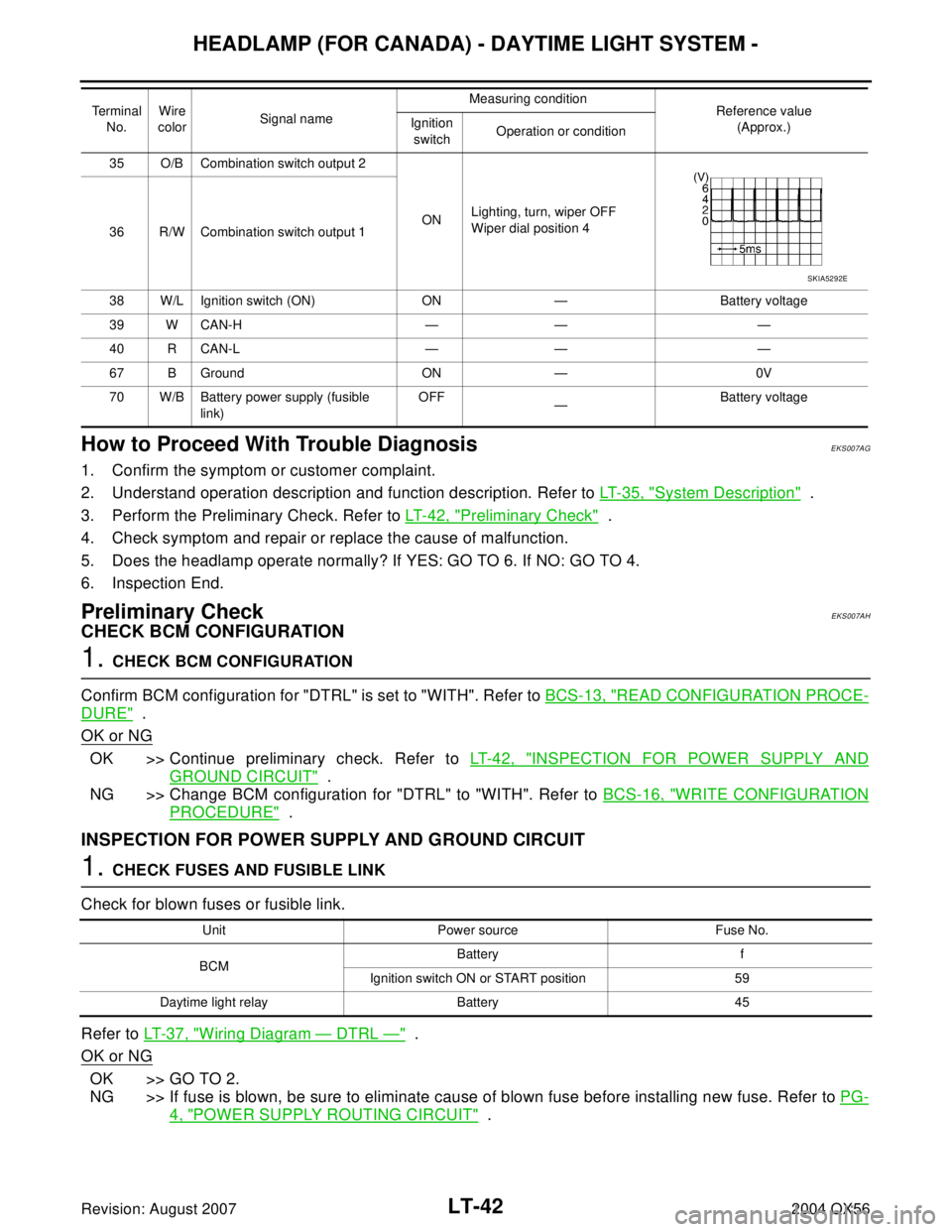
35 O/B Combination switch output 2
ONLighting, turn, wiper OFF
Wiper dial position 4
36 R/W Combination switch output 1
38 W/L Ignition switch (ON) ON — Battery voltage
39 W CAN-H — — —
40 R CAN-L — — —
67 B Ground ON — 0V
70 W/B Battery power supply (fusible
link)OFF
—Battery voltage Terminal
No.Wire
colorSignal nameMeasuring condition
Reference value
(Approx.) Ignition
switchOperation or condition
SKIA5292E
Unit Power source Fuse No.
BCMBattery f
Ignition switch ON or START position 59
Daytime light relay Battery 45
Page 2474 of 3371

HEADLAMP (FOR CANADA) - DAYTIME LIGHT SYSTEM -
LT-43
C
D
E
F
G
H
I
J
L
MA
B
LT
Revision: August 20072004 QX56
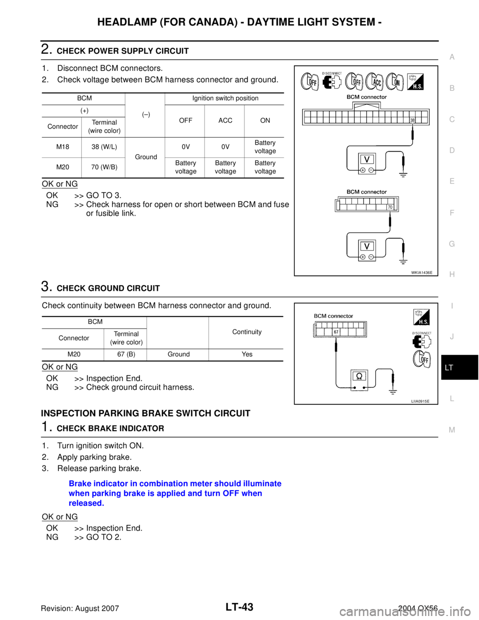
2. CHECK POWER SUPPLY CIRCUIT
1. Disconnect BCM connectors.
2. Check voltage between BCM harness connector and ground.
OK or NG
OK >> GO TO 3.
NG >> Check harness for open or short between BCM and fuse
or fusible link.
3. CHECK GROUND CIRCUIT
Check continuity between BCM harness connector and ground.
OK or NG
OK >> Inspection End.
NG >> Check ground circuit harness.
INSPECTION PARKING BRAKE SWITCH CIRCUIT
1. CHECK BRAKE INDICATOR
1. Turn ignition switch ON.
2. Apply parking brake.
3. Release parking brake.
OK or NG
OK >> Inspection End.
NG >> GO TO 2.
BCM
(–)Ignition switch position
(+)
OFF ACC ON
ConnectorTerminal
(wire color)
M18 38 (W/L)
Ground0V 0VBattery
voltage
M20 70 (W/B)Battery
voltageBattery
voltageBattery
voltage
WKIA1436E
BCM
Continuity
ConnectorTe r m i n a l
(wire color)
M20 67 (B) Ground Yes
LIIA0915E
Brake indicator in combination meter should illuminate
when parking brake is applied and turn OFF when
released.
Page 2475 of 3371

LT-44
HEADLAMP (FOR CANADA) - DAYTIME LIGHT SYSTEM -
Revision: August 20072004 QX56
2. CHECK PARKING BRAKE SWITCH SIGNAL
1. Disconnect parking brake switch connector.
2. Turn ignition switch ON.
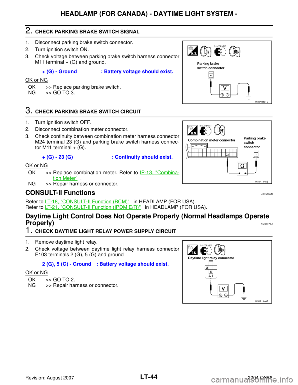
3. Check voltage between parking brake switch harness connector
M11 terminal + (G) and ground.
OK or NG
OK >> Replace parking brake switch.
NG >> GO TO 3.
3. CHECK PARKING BRAKE SWITCH CIRCUIT
1. Turn ignition switch OFF.
2. Disconnect combination meter connector.
3. Check continuity between combination meter harness connector
M24 terminal 23 (G) and parking brake switch harness connec-
tor M11 terminal + (G).
OK or NG
OK >> Replace combination meter. Refer to IP-13, "Combina-
tion Meter" .
NG >> Repair harness or connector.
CONSULT-II FunctionsEKS007AI
Refer to LT- 1 8 , "CONSULT-II Function (BCM)" in HEADLAMP (FOR USA).
Refer to LT- 2 1 , "
CONSULT-II Function (IPDM E/R)" in HEADLAMP (FOR USA).
Daytime Light Control Does Not Operate Properly (Normal Headlamps Operate
Properly)
EKS007AJ
1. CHECK DAYTIME LIGHT RELAY POWER SUPPLY CIRCUIT
1. Remove daytime light relay.
2. Check voltage between daytime light relay harness connector
E103 terminals 2 (G), 5 (G) and ground
OK or NG
OK >> GO TO 2.
NG >> Repair harness or connector.+ (G) - Ground : Battery voltage should exist.
WKIA0481E
+ (G) - 23 (G) : Continuity should exist.
WKIA1445E
2 (G), 5 (G) - Ground : Battery voltage should exist.
WKIA1446E