2004 INFINITI QX56 Light
[x] Cancel search: LightPage 2505 of 3371
LT-74
FRONT FOG LAMP
Revision: August 20072004 QX56
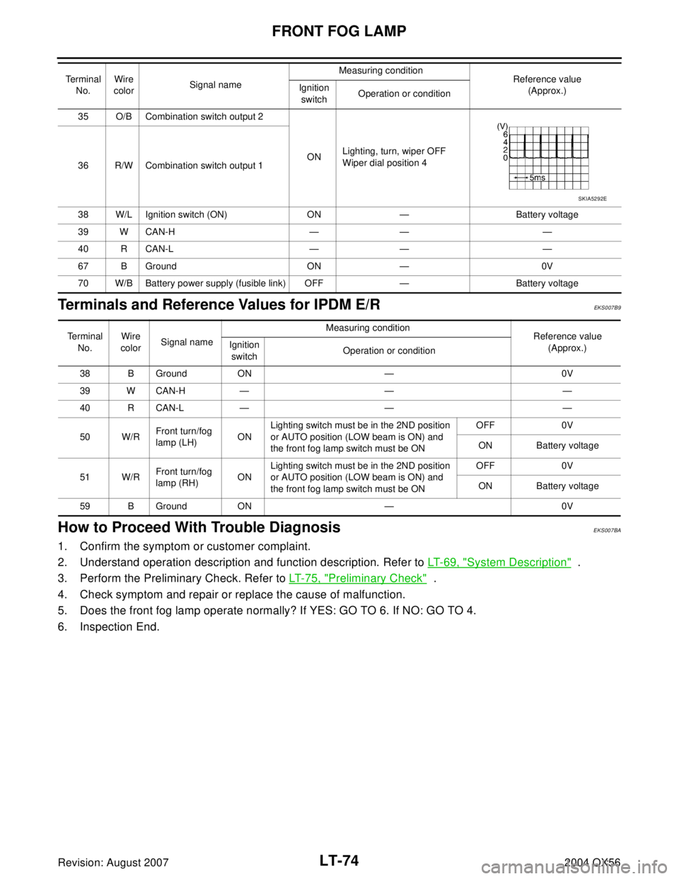
Terminals and Reference Values for IPDM E/REKS007B9
How to Proceed With Trouble DiagnosisEKS007BA
1. Confirm the symptom or customer complaint.
2. Understand operation description and function description. Refer to LT-69, "
System Description" .
3. Perform the Preliminary Check. Refer to LT-75, "
Preliminary Check" .
4. Check symptom and repair or replace the cause of malfunction.
5. Does the front fog lamp operate normally? If YES: GO TO 6. If NO: GO TO 4.
6. Inspection End.
35 O/B Combination switch output 2
ONLighting, turn, wiper OFF
Wiper dial position 4
36 R/W Combination switch output 1
38 W/L Ignition switch (ON) ON — Battery voltage
39 W CAN-H — — —
40 R CAN-L — — —
67 B Ground ON — 0V
70 W/B Battery power supply (fusible link) OFF — Battery voltage Terminal
No.Wire
colorSignal nameMeasuring condition
Reference value
(Approx.) Ignition
switchOperation or condition
SKIA5292E
Te r m i n a l
No.Wire
colorSignal nameMeasuring condition
Reference value
(Approx.) Ignition
switchOperation or condition
38 B Ground ON — 0V
39 W CAN-H — — —
40 R CAN-L — — —
50 W/RFront turn/fog
lamp (LH)ONLighting switch must be in the 2ND position
or AUTO position (LOW beam is ON) and
the front fog lamp switch must be ONOFF 0V
ON Battery voltage
51 W/RFront turn/fog
lamp (RH) ONLighting switch must be in the 2ND position
or AUTO position (LOW beam is ON) and
the front fog lamp switch must be ONOFF 0V
ON Battery voltage
59 B Ground ON — 0V
Page 2507 of 3371
LT-76
FRONT FOG LAMP
Revision: August 20072004 QX56
CONSULT-II FunctionsEKS007BC
Refer to LT- 1 8 , "CONSULT-II Function (BCM)" in HEADLAMP (FOR USA).
Refer to LT- 2 1 , "
CONSULT-II Function (IPDM E/R)" in HEADLAMP (FOR USA).
Front Fog Lamps Do Not Illuminate (Both Sides)EKS007BD
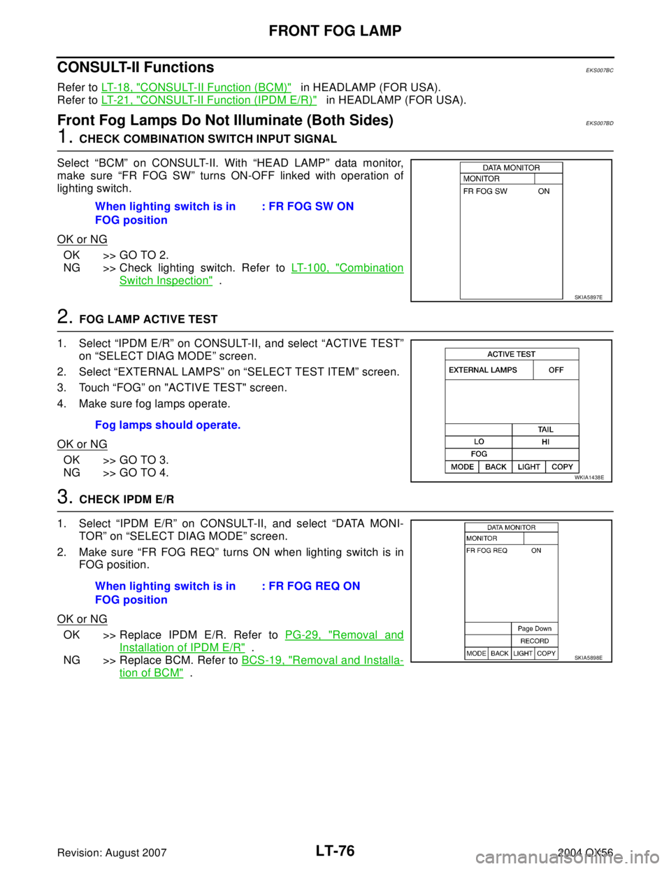
1. CHECK COMBINATION SWITCH INPUT SIGNAL
Select “BCM” on CONSULT-II. With “HEAD LAMP” data monitor,
make sure “FR FOG SW” turns ON-OFF linked with operation of
lighting switch.
OK or NG
OK >> GO TO 2.
NG >> Check lighting switch. Refer to LT-100, "
Combination
Switch Inspection" .
2. FOG LAMP ACTIVE TEST
1. Select “IPDM E/R” on CONSULT-II, and select “ACTIVE TEST”
on “SELECT DIAG MODE” screen.
2. Select “EXTERNAL LAMPS” on “SELECT TEST ITEM” screen.
3. Touch “FOG” on "ACTIVE TEST" screen.
4. Make sure fog lamps operate.
OK or NG
OK >> GO TO 3.
NG >> GO TO 4.
3. CHECK IPDM E/R
1. Select “IPDM E/R” on CONSULT-II, and select “DATA MONI-
TOR” on “SELECT DIAG MODE” screen.
2. Make sure “FR FOG REQ” turns ON when lighting switch is in
FOG position.
OK or NG
OK >> Replace IPDM E/R. Refer to PG-29, "Removal and
Installation of IPDM E/R" .
NG >> Replace BCM. Refer to BCS-19, "
Removal and Installa-
tion of BCM" . When lighting switch is in
FOG position: FR FOG SW ON
SKIA5897E
Fog lamps should operate.
WKIA1438E
When lighting switch is in
FOG position: FR FOG REQ ON
SKIA5898E
Page 2516 of 3371
TURN SIGNAL AND HAZARD WARNING LAMPS
LT-85
C
D
E
F
G
H
I
J
L
MA
B
LT
Revision: August 20072004 QX56
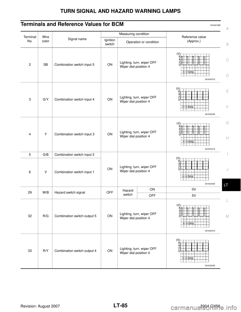
Terminals and Reference Values for BCMEKS007BM
Terminal
No.Wire
colorSignal nameMeasuring condition
Reference value
(Approx.) Ignition
switchOperation or condition
2 SB Combination switch input 5 ONLighting, turn, wiper OFF
Wiper dial position 4
3 G/Y Combination switch input 4 ONLighting, turn, wiper OFF
Wiper dial position 4
4 Y Combination switch input 3 ONLighting, turn, wiper OFF
Wiper dial position 4
5 G/B Combination switch input 2
ONLighting, turn, wiper OFF
Wiper dial position 4
6 V Combination switch input 1
29 W/B Hazard switch signal OFFHazard
switchON 0V
OFF 5V
32 R/G Combination switch output 5 ONLighting, turn, wiper OFF
Wiper dial position 4
33 R/Y Combination switch output 4 ONLighting, turn, wiper OFF
Wiper dial position 4
SKIA5291E
SKIA5292E
SKIA5291E
SKIA5292E
SKIA5291E
SKIA5292E
Page 2517 of 3371

LT-86
TURN SIGNAL AND HAZARD WARNING LAMPS
Revision: August 20072004 QX56
How to Proceed With Trouble DiagnosisEKS007BN
1. Confirm the symptom or customer complaint.
2. Understand operation description and function description. Refer to LT-80, "
System Description" .
3. Perform preliminary check. Refer to LT-87, "
Preliminary Check" .
4. Check symptom and repair or replace the cause of malfunction.
5. Do turn signal and hazard warning lamps operate normally? If YES: GO TO 6. If NO: GO TO 4.
6. Inspection End.
34 L Combination switch output 3 ONLighting, turn, wiper OFF
Wiper dial position 4
35 O/B Combination switch output 2
ONLighting, turn, wiper OFF
Wiper dial position 4
36 R/W Combination switch output 1
38 W/L Ignition switch (ON) ON — Battery voltage
39 W CAN-H — — —
40 R CAN-L — — —
60 G/B Turn signal (left) ONCombina-
tion switchTu rn le ft O N
61 G/Y Turn signal (right) ONCombina-
tion switchTurn right ON
67 B Ground ON — 0V
70 W/B Battery power supply OFF — Battery voltage Te r m i n a l
No.Wire
colorSignal nameMeasuring condition
Reference value
(Approx.) Ignition
switchOperation or condition
SKIA5291E
SKIA5292E
SKIA3009J
SKIA3009J
Page 2520 of 3371
TURN SIGNAL AND HAZARD WARNING LAMPS
LT-89
C
D
E
F
G
H
I
J
L
MA
B
LT
Revision: August 20072004 QX56
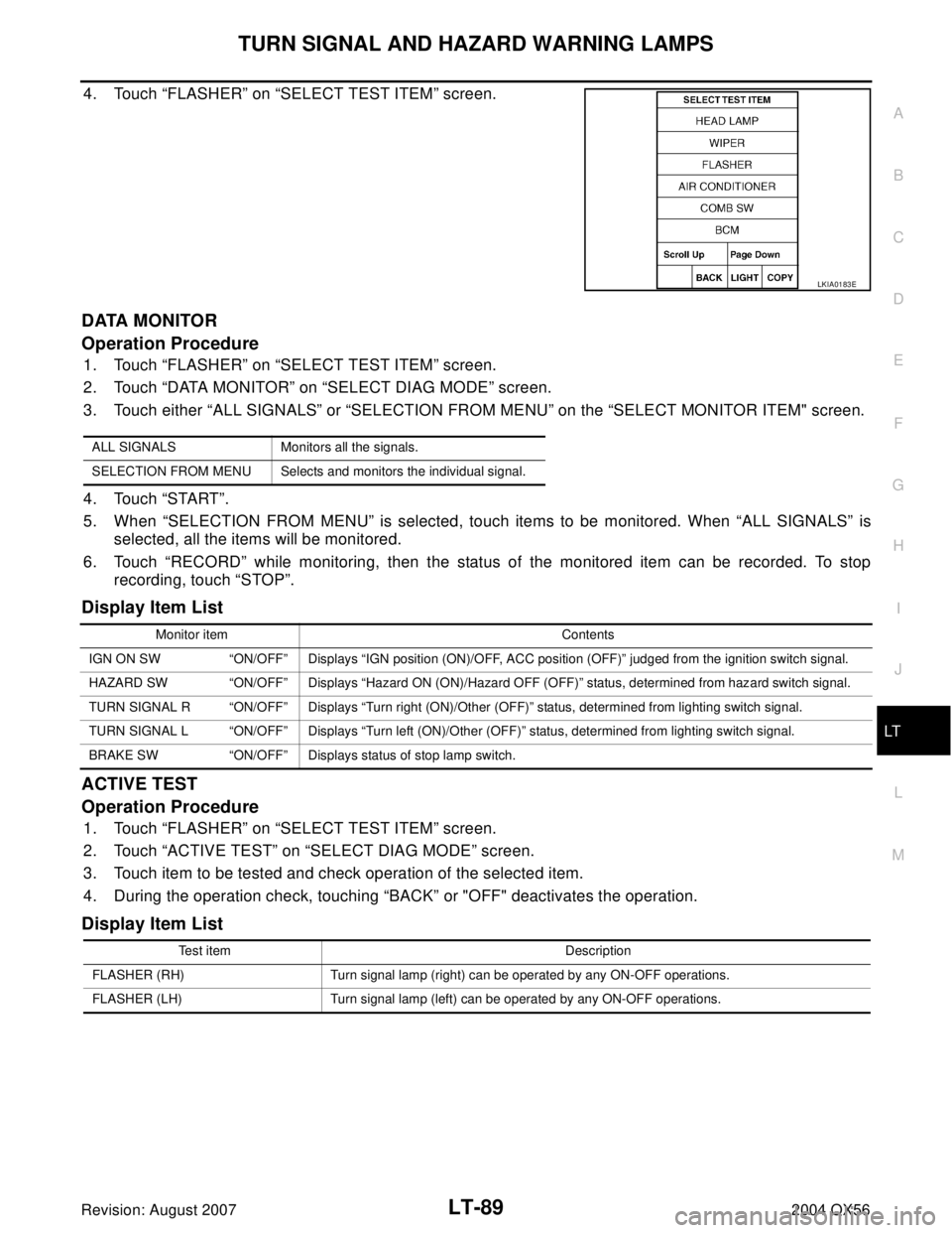
4. Touch “FLASHER” on “SELECT TEST ITEM” screen.
DATA MONITOR
Operation Procedure
1. Touch “FLASHER” on “SELECT TEST ITEM” screen.
2. Touch “DATA MONITOR” on “SELECT DIAG MODE” screen.
3. Touch either “ALL SIGNALS” or “SELECTION FROM MENU” on the “SELECT MONITOR ITEM" screen.
4. Touch “START”.
5. When “SELECTION FROM MENU” is selected, touch items to be monitored. When “ALL SIGNALS” is
selected, all the items will be monitored.
6. Touch “RECORD” while monitoring, then the status of the monitored item can be recorded. To stop
recording, touch “STOP”.
Display Item List
ACTIVE TEST
Operation Procedure
1. Touch “FLASHER” on “SELECT TEST ITEM” screen.
2. Touch “ACTIVE TEST” on “SELECT DIAG MODE” screen.
3. Touch item to be tested and check operation of the selected item.
4. During the operation check, touching “BACK” or "OFF" deactivates the operation.
Display Item List
LKIA0183E
ALL SIGNALS Monitors all the signals.
SELECTION FROM MENU Selects and monitors the individual signal.
Monitor item Contents
IGN ON SW “ON/OFF” Displays “IGN position (ON)/OFF, ACC position (OFF)” judged from the ignition switch signal.
HAZARD SW “ON/OFF” Displays “Hazard ON (ON)/Hazard OFF (OFF)” status, determined from hazard switch signal.
TURN SIGNAL R “ON/OFF” Displays “Turn right (ON)/Other (OFF)” status, determined from lighting switch signal.
TURN SIGNAL L “ON/OFF” Displays “Turn left (ON)/Other (OFF)” status, determined from lighting switch signal.
BRAKE SW “ON/OFF” Displays status of stop lamp switch.
Test item Description
FLASHER (RH) Turn signal lamp (right) can be operated by any ON-OFF operations.
FLASHER (LH) Turn signal lamp (left) can be operated by any ON-OFF operations.
Page 2521 of 3371
LT-90
TURN SIGNAL AND HAZARD WARNING LAMPS
Revision: August 20072004 QX56
Turn Signal Lamp Does Not OperateEKS007BQ
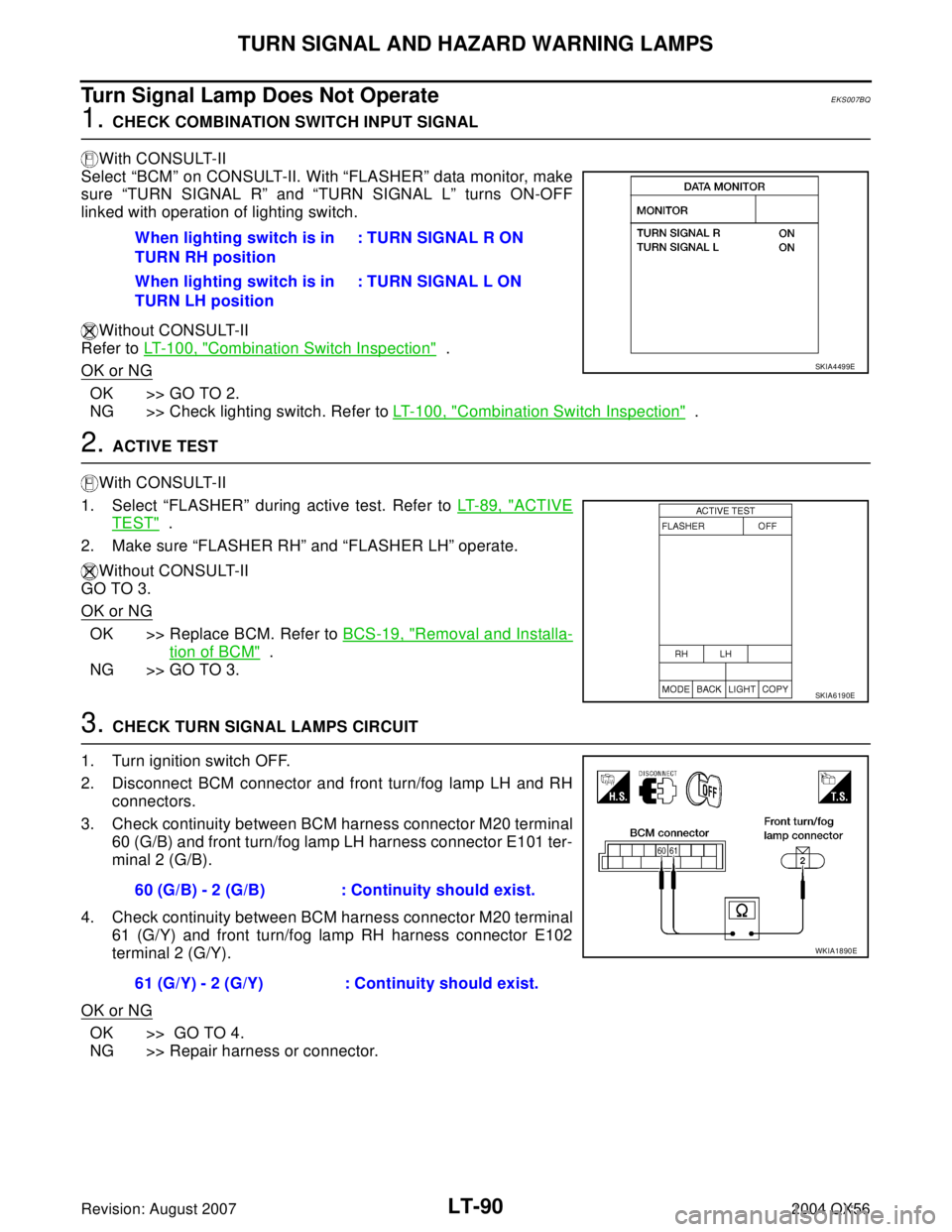
1. CHECK COMBINATION SWITCH INPUT SIGNAL
With CONSULT-II
Select “BCM” on CONSULT-II. With “FLASHER” data monitor, make
sure “TURN SIGNAL R” and “TURN SIGNAL L” turns ON-OFF
linked with operation of lighting switch.
Without CONSULT-II
Refer to LT- 1 0 0 , "
Combination Switch Inspection" .
OK or NG
OK >> GO TO 2.
NG >> Check lighting switch. Refer to LT-100, "
Combination Switch Inspection" .
2. ACTIVE TEST
With CONSULT-II
1. Select “FLASHER” during active test. Refer to LT-89, "
ACTIVE
TEST" .
2. Make sure “FLASHER RH” and “FLASHER LH” operate.
Without CONSULT-II
GO TO 3.
OK or NG
OK >> Replace BCM. Refer to BCS-19, "Removal and Installa-
tion of BCM" .
NG >> GO TO 3.
3. CHECK TURN SIGNAL LAMPS CIRCUIT
1. Turn ignition switch OFF.
2. Disconnect BCM connector and front turn/fog lamp LH and RH
connectors.
3. Check continuity between BCM harness connector M20 terminal
60 (G/B) and front turn/fog lamp LH harness connector E101 ter-
minal 2 (G/B).
4. Check continuity between BCM harness connector M20 terminal
61 (G/Y) and front turn/fog lamp RH harness connector E102
terminal 2 (G/Y).
OK or NG
OK >> GO TO 4.
NG >> Repair harness or connector.When lighting switch is in
TURN RH position: TURN SIGNAL R ON
When lighting switch is in
TURN LH position: TURN SIGNAL L ON
SKIA4499E
SKIA6190E
60 (G/B) - 2 (G/B) : Continuity should exist.
61 (G/Y) - 2 (G/Y) : Continuity should exist.
WKIA1890E
Page 2526 of 3371
LIGHTING AND TURN SIGNAL SWITCH
LT-95
C
D
E
F
G
H
I
J
L
MA
B
LT
Revision: August 20072004 QX56
LIGHTING AND TURN SIGNAL SWITCHPFP:25540
Removal and InstallationEKS007BY
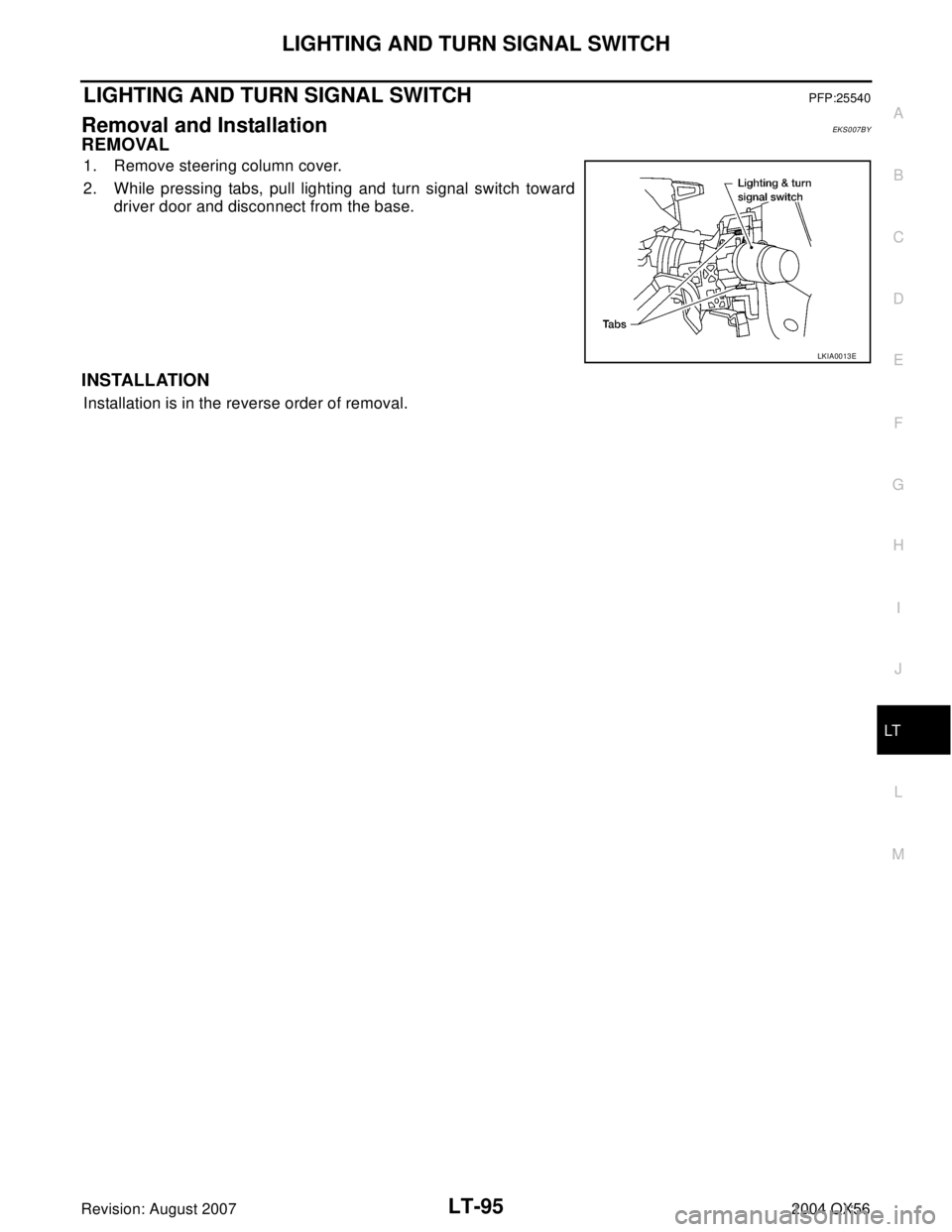
REMOVAL
1. Remove steering column cover.
2. While pressing tabs, pull lighting and turn signal switch toward
driver door and disconnect from the base.
INSTALLATION
Installation is in the reverse order of removal.
LKIA0013E
Page 2530 of 3371

COMBINATION SWITCH
LT-99
C
D
E
F
G
H
I
J
L
MA
B
LT
Revision: August 20072004 QX56
4. Touch “COMB SW” on “SELECT TEST ITEM” screen.
DATA MONITOR
Operation Procedure
1. Touch “COMB SW” on “SELECT TEST ITEM” screen.
2. Touch “DATA MONITOR” on “SELECT DIAG MODE” screen.
3. Touch either “ALL SIGNALS” or “SELECTION FROM MENU” on “SELECT MONITOR ITEM” screen.
4. Touch “START”.
5. When “SELECTION FROM MENU” is selected, touch items to be monitored. When “ALL SIGNALS” is
selected, all the signals will be monitored.
6. Touch “RECORD” while monitoring, then the status of the monitored item can be recorded. To stop
recording, touch “STOP”.
Display Item List
LKIA0283E
ALL SIGNALS Monitors all the signals.
SELECTION FROM MENU Selects and monitors individual signal.
Monitor item name
“OPERATION OR UNIT”Contents
TURN SIGNAL R “ON/OFF” Displays “Turn Right (ON)/Other (OFF)” status, determined from lighting switch signal.
TURN SIGNAL L “ON/OFF” Displays “Turn Left (ON)/Other (OFF)” status, determined from lighting switch signal.
HI BEAM SW “ON/OFF”Displays status (high beam switch: ON/Others: OFF) of high beam switch judged from lighting
switch signal.
HEAD LAMP SW 1 “ON/OFF” Displays “Headlamp switch 1 (ON)/Other (OFF)” status, determined from lighting switch signal.
HEAD LAMP SW 2 “ON/OFF”Displays status (headlamp switch 2: ON/Others: OFF) of headlamp switch 2 judged from lighting
switch signal.
LIGHT SW 1ST “ON/OFF”Displays status (lighting switch 1st position: ON/Others: OFF) of lighting switch judged from lighting
switch signal.
PASSING SW “ON/OFF”Displays status (flash-to-pass switch: ON/Others: OFF) of flash-to-pass switch judged from lighting
switch signal.
AUTO LIGHT SW “ON/OFF” Displays “Auto light switch (ON)/Other (OFF)” status, determined from lighting switch signal.
FR FOG SW “ON/OFF” Displays “Front fog lamp switch (ON)/Other (OFF)” status, determined from lighting switch signal.
FR WIPER HI “ON/OFF” Displays “Front Wiper HI (ON)/Other (OFF)” status, determined from wiper switch signal.
FR WIPER LOW “ON/OFF” Displays “Front Wiper LOW (ON)/Other (OFF)” status, determined from wiper switch signal.
FR WIPER INT “ON/OFF” Displays “Front Wiper INT (ON)/Other (OFF)” status, determined from wiper switch signal.
FR WASHER SW “ON/OFF” Displays “Front Washer Switch (ON)/Other (OFF)” status, determined from wiper switch signal.
INT VOLUME [1 - 7] Displays intermittent operation knob setting (1 - 7), determined from wiper switch signal.
RR WIPER ON “ON/OFF” Displays “Rear Wiper (ON)/(OFF)” status, determined from wiper switch signal.
RR WIPER INT “ON/OFF” Displays “Rear Wiper INT (ON)/(OFF)” status, determined from wiper switch signal.
RR WASHER SW "ON/OFF" Displays "Rear Washer (ON)/(OFF)" status, determined from wiper switch signal.