Page 2681 of 3371

PG-22
IPDM E/R (INTELLIGENT POWER DISTRIBUTION MODULE ENGINE ROOM)
Revision: August 20072004 QX56
All Signals, Main Signals, Selection From Menu
NOTE:
Perform monitoring of IPDM E/R data with the ignition switch ON. When the ignition switch is in ACC position,
display may not be correct.
ACTIVE TEST
Operation Procedure
1. Touch “ACTIVE TEST” on “SELECT DIAG-MODE” screen.
2. Touch item to be tested, and check operation.
3. Touch “START”.
4. Touch "STOP" while testing to stop the operation.
Item nameCONSULT-II
screen displayDisplay or unitMonitor item selection
Description
ALL
SIGNALSMAIN
SIGNALSSELECTION
FROM MENU
Motor fan requestMOTOR FAN
REQ1/2/3/4 X X X Signal status input from ECM
Compressor request AC COMP REQ ON/OFF X X X Signal status input from ECM
Position lights
requestTAIL & CLR REQ ON/OFF X X X Signal status input from BCM
Headlamp low beam
requestHL LO REQ ON/OFF X X X Signal status input from BCM
Headlamp high
beam requestHL HI REQ ON/OFF X X X Signal status input from BCM
Front fog lghts
requestFR FOG REQ ON/OFF X X X Signal status input from BCM
Front wiper request FR WIP REQSTOP/1LOW/
LOW/HIX X X Signal status input from BCM
Wiper auto stopWIP AUTO
STOPACT P/STOP P X X X Output status of IPDM E/R
Wiper protection WIP PROT OFF/Block X X X Control status of IPDM E/R
Starter request ST RLY REQ ON/OFF X X
Status of input signal
NOTE
Ignition relay
statusIGN RLY ON/OFF X X XIgnition relay status monitored
with IPDM E/R
Rear defogger
requestRR DEF REQ ON/OFF X X X Signal status input from BCM
Oil pressure switch OIL P SW OPEN/CLOSE X XSignal status input from IPDM
E/R (function is not enabled)
Hood switch HOOD SW OFF XSignal status input from IPDM
E/R (function is not enabled)
Theft warning horn
requestTHFT HRN REQ ON/OFF X X Signal status input from BCM
Horn chirp HORN CHIRP ON/OFF X X Output status of IPDM E/R
Daytime running
lamp requestDTRL REQ ON/OFF X X Signal status input from BCM
Test name CONSULT-II screen display Description
Rear defogger output REAR DEFOGGERWith a certain ON-OFF operation, the rear defogger relay can be oper-
ated.
Front wiper (HI, LO) output FRONT WIPERWith a certain operation (OFF, HI, LO), the front wiper relay (Lo, Hi)
can be operated.
Cooling fan output MOTOR FAN With a certain operation (1, 2, 3, 4), the cooling fan can be operated.
Lamp (HI, LO, TAIL, FOG)
outputEXTERNAL LAMPSWith a certain operation (OFF, TAIL, LO, HI, FOG), the lamp relay
(Low, High, Tail, Fog) can be operated.
Page 2720 of 3371

HARNESS
PG-61
C
D
E
F
G
H
I
J
L
MA
B
PG
Revision: August 20072004 QX56
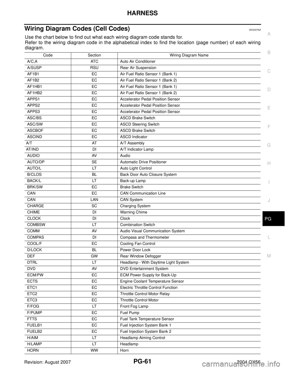
Wiring Diagram Codes (Cell Codes)EKS007NZ
Use the chart below to find out what each wiring diagram code stands for.
Refer to the wiring diagram code in the alphabetical index to find the location (page number) of each wiring
diagram.
Code Section Wiring Diagram Name
A/C,A ATC Auto Air Conditioner
A/SUSP RSU Rear Air Suspension
AF1B1 EC Air Fuel Ratio Sensor 1 (Bank 1)
AF1B2 EC Air Fuel Ratio Sensor 1 (Bank 2)
AF1HB1 EC Air Fuel Ratio Sensor 1 (Bank 1)
AF1HB2 EC Air Fuel Ratio Sensor 1 (Bank 2)
APPS1 EC Accelerator Pedal Position Sensor
APPS2 EC Accelerator Pedal Position Sensor
APPS3 EC Accelerator Pedal Position Sensor
ASC/BS EC ASCD Brake Switch
ASC/SW EC ASCD Steering Switch
ASCBOF EC ASCD Brake Switch
ASCIND EC ASCD Indicator
A/T AT A/T Assembly
AT/IND DI A/T Indicator Lamp
AUDIO AV Audio
AUTO/DP SE Automatic Drive Positioner
AUTO/L LT Auto Light Control
B/CLOS BL Back Door Auto Closure System
BACK/L LT Back-up Lamp
BRK/SW EC Brake Switch
CAN EC CAN Communication Line
CAN LAN CAN System
CHARGE SC Charging System
CHIME DI Warning Chime
CLOCK DI Clock
COMBSW LT Combination Switch
COMM AV Audio Visual Communication System
COMPAS DI Compass and Thermometer
COOL/F EC Cooling Fan Control
D/LOCK BL Power Door Lock
DEF GW Rear Window Defogger
DTRL LT Headlamp - With Daytime Light System
DVD AV DVD Entertainment System
ECM/PW EC ECM Power Supply for Back-Up
ECTS EC Engine Coolant Temperature Sensor
ETC1 EC Electric Throttle Control Function
ETC2 EC Throttle Control Motor Relay
ETC3 EC Throttle Control Motor
F/FOG LT Front Fog Lamp
F/PUMP EC Fuel Pump
FTTS EC Fuel Tank Temperature Sensor
FUELB1 EC Fuel Injection System Bank 1
FUELB2 EC Fuel Injection System Bank 2
H/AIM LT Headlamp Aiming Control
H/LAMP LT Headlamp
HORN WW Horn
Page 2743 of 3371
PR-6
FRONT PROPELLER SHAFT
Revision: August 20072004 QX56
2. Remove the snap ring.
3. Push out and remove the journal bearing by lightly tapping the
yoke with a hammer, taking care not to damage the journal or
yoke hole.
4. Remove the bearing at the opposite side in above operation.
NOTE:
Put marks on the disassembled parts so that they can be rein-
stalled in their original positions from which they were removed.
ASSEMBLY
Journal
1. Assemble the journal bearings. Apply multipurpose grease on
the bearing inner surface.
NOTE:
During assembly, use caution so that the needle bearings do not
fall down.
APD0 11
SPD7 32
SPD1 31
WPD019
Page 2747 of 3371
PR-10
REAR PROPELLER SHAFT
Revision: August 20072004 QX56
Disassembly and AssemblyEDS002K4
DISASSEMBLY
Journal
1. Put matching marks on the rear propeller shaft and flange yoke
as shown.
CAUTION:
For matching marks use paint. Never damage the rear pro-
peller shaft or flange yoke.
2. Remove the snap ring.
3. Push out and remove the journal bearing by lightly tapping the
yoke with a hammer, taking care not to damage the journal or
yoke hole.
4. Remove the bearing at the opposite side of above operation.
NOTE:
Put marks on the disassembled parts so that they can be rein-
stalled in their original positions from which they were removed.
SPD1 28
APD0 11
SPD7 32
SPD1 31
Page 2750 of 3371
SERVICE DATA AND SPECIFICATIONS (SDS)
PR-13
C
E
F
G
H
I
J
K
L
MA
B
PR
Revision: August 20072004 QX56
Snap RingEDS002K6
Model 2F1310
Unit: mm (in)
*Always check with the Parts Department for the latest parts information.
Model 2S1350
Unit: mm (in)
*Always check with the Parts Department for the latest parts information.Thickness Color Part Number*
1.99 (0.0783) White 37146-C9400
2.02 (0.0795) Yellow 37147-C9400
2.05 (0.0807) Red 37148-C9400
2.08 (0.0819) Green 37149-C9400
2.11 (0.0831) Blue 37150-C9400
2.14 (0.0843) Light brown 37151-C9400
2.17 (0.0854) Black 37152-C9400
2.20 (0.0866) No paint 37153-C9400
Thickness Color Part Number*
1.600 - 1.638 (0.0630 - 0.0645) Black 37146-7S000
1.549 - 1.588 (0.0610 - 0.0625) Black 37147-7S000
1.524 - 1.562 (0.0600 - 0.0615) Black 37148-7S000
1.499 - 1.537 (0.0590 - 0.0605) Black 37149-7S000
Page 2758 of 3371

STEERING WHEEL
PS-7
C
D
E
F
H
I
J
K
L
MA
B
PS
Revision: August 20072004 QX56
STEERING WHEELPFP:48430
On-Vehicle Inspection and ServiceEGS000MQ
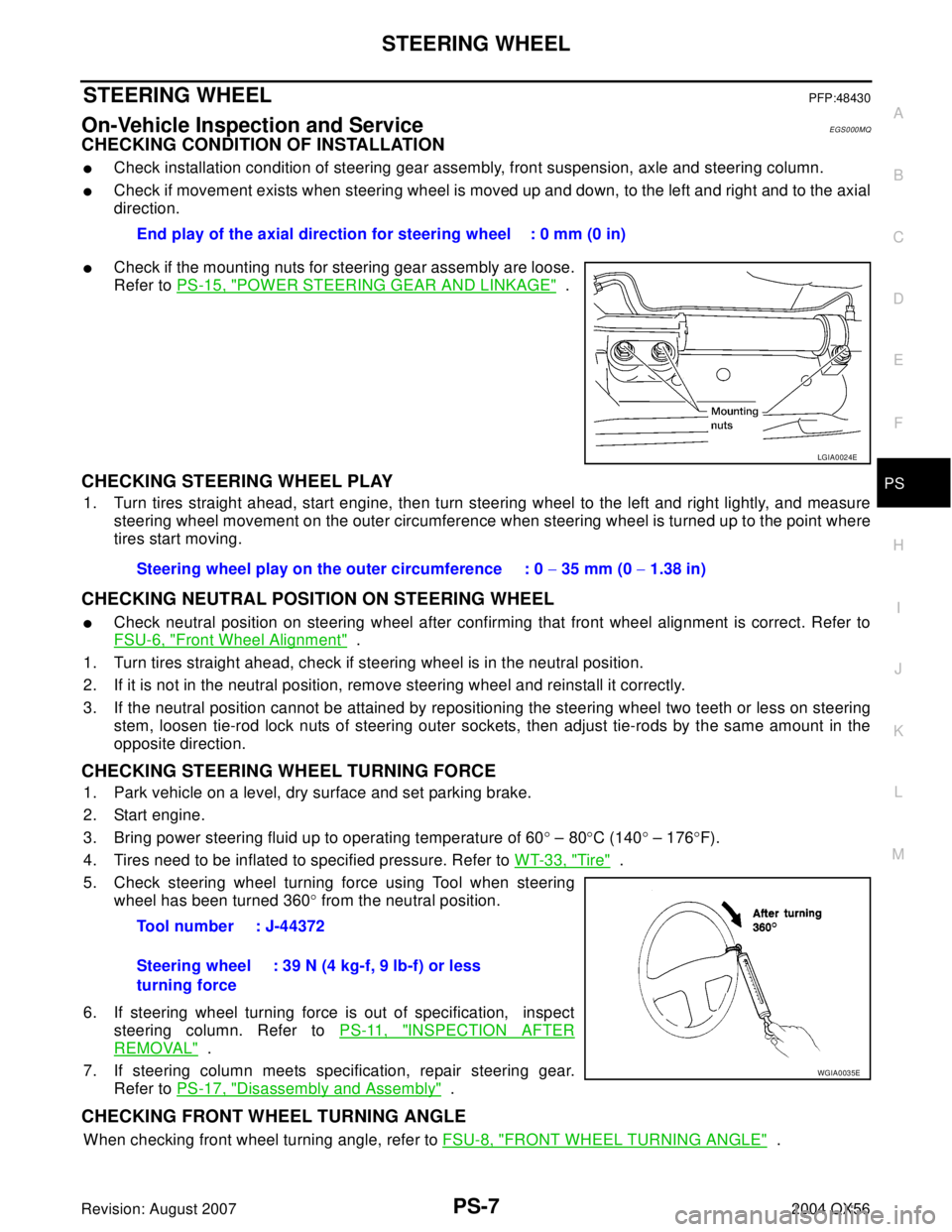
CHECKING CONDITION OF INSTALLATION
�Check installation condition of steering gear assembly, front suspension, axle and steering column.
�Check if movement exists when steering wheel is moved up and down, to the left and right and to the axial
direction.
�Check if the mounting nuts for steering gear assembly are loose.
Refer to PS-15, "
POWER STEERING GEAR AND LINKAGE" .
CHECKING STEERING WHEEL PLAY
1. Turn tires straight ahead, start engine, then turn steering wheel to the left and right lightly, and measure
steering wheel movement on the outer circumference when steering wheel is turned up to the point where
tires start moving.
CHECKING NEUTRAL POSITION ON STEERING WHEEL
�Check neutral position on steering wheel after confirming that front wheel alignment is correct. Refer to
FSU-6, "
Front Wheel Alignment" .
1. Turn tires straight ahead, check if steering wheel is in the neutral position.
2. If it is not in the neutral position, remove steering wheel and reinstall it correctly.
3. If the neutral position cannot be attained by repositioning the steering wheel two teeth or less on steering
stem, loosen tie-rod lock nuts of steering outer sockets, then adjust tie-rods by the same amount in the
opposite direction.
CHECKING STEERING WHEEL TURNING FORCE
1. Park vehicle on a level, dry surface and set parking brake.
2. Start engine.
3. Bring power steering fluid up to operating temperature of 60° – 80°C (140° – 176°F).
4. Tires need to be inflated to specified pressure. Refer to WT-33, "
Tire" .
5. Check steering wheel turning force using Tool when steering
wheel has been turned 360° from the neutral position.
6. If steering wheel turning force is out of specification, inspect
steering column. Refer to PS-11, "
INSPECTION AFTER
REMOVAL" .
7. If steering column meets specification, repair steering gear.
Refer to PS-17, "
Disassembly and Assembly" .
CHECKING FRONT WHEEL TURNING ANGLE
When checking front wheel turning angle, refer to FSU-8, "FRONT WHEEL TURNING ANGLE" . End play of the axial direction for steering wheel : 0 mm (0 in)
LGIA0024E
Steering wheel play on the outer circumference : 0 − 35 mm (0 − 1.38 in)
Tool number : J-44372
Steering wheel
turning force: 39 N (4 kg-f, 9 lb-f) or less
WGIA0035E
Page 2773 of 3371
![INFINITI QX56 2004 Factory Service Manual PS-22
POWER STEERING GEAR AND LINKAGE
Revision: August 20072004 QX56
a. To avoid damaging inner rack oil seal, wrap an OHP sheet
[approximately 70 mm (2.76 in) × 100 mm (3.94 in)] around rack
teeth. INFINITI QX56 2004 Factory Service Manual PS-22
POWER STEERING GEAR AND LINKAGE
Revision: August 20072004 QX56
a. To avoid damaging inner rack oil seal, wrap an OHP sheet
[approximately 70 mm (2.76 in) × 100 mm (3.94 in)] around rack
teeth.](/manual-img/42/57034/w960_57034-2772.png)
PS-22
POWER STEERING GEAR AND LINKAGE
Revision: August 20072004 QX56
a. To avoid damaging inner rack oil seal, wrap an OHP sheet
[approximately 70 mm (2.76 in) × 100 mm (3.94 in)] around rack
teeth. Place oil seal on sheet. Then, pull oil seal along with OHP
sheet until they pass the toothed section of rack, then remove
sheet.
b. Insert rack oil seal (inner) to piston (rack Teflon® ring) position
and push retainer to adjust screw side with fingers lightly. Then
make rack move in gear housing assembly and install rack oil
seal (inner) to fit with gear housing assembly.
c. When installing outer rack oil seal, cover the end of rack with an
OHP sheet [70 mm (2.76 in) × 100 mm (3.94 in)]. It will avoid
damaging rack oil seal. Then place oil seal on sheet. Pull rack oil
seal along with OHP sheet until they pass rack end, then
remove sheet.
d. Install end cover assembly to rack, move it to gear housing assembly.
5. Using a 45 mm (1.77 in) open head wrench or suitable tool,
tighten end cover assembly to specification.
CAUTION:
Do not damage rack surface. If it is damaged, it may cause
oil leaks. Replace rack assembly.
SGIA0155E
WGIA0095E
SGIA0157E
SST 0 81 B
Page 2776 of 3371
POWER STEERING GEAR AND LINKAGE
PS-25
C
D
E
F
H
I
J
K
L
MA
B
PS
Revision: August 20072004 QX56
21. Install new boot clamps and crimp securely using Tool.
CAUTION:
Do not reuse boot clamps.
22. Install cylinder tubes to gear housing assembly.
23. Install lock nut and outer socket to inner socket.
24. Tighten lightly tie-rod in specified length “L”, then tighten lock nut
at specified torque. Refer to PS-17, "
Disassembly and Assem-
bly" . Reconfirm if tie-rod length is within limit of specified length
“L”.
CAUTION:
Perform toe-in adjustment after this procedure. Length
achieved after toe-in adjustment is not necessarily the
value given here.Tool number : KV40107300 ( — )
AST 1 39
Inner socket length “L” : 115.2 mm (4.54 in)
SGIA0167E