Page 462 of 3371

TROUBLE DIAGNOSIS
ATC-57
C
D
E
F
G
H
I
K
L
MA
B
AT C
Revision: August 20072004 QX56
CHECKING DISCHARGE AIR
1. Press MODE switch four times and then rotate the DEF dial
counterclockwise.
2. Each position indicator should change shape (on display).
3. Confirm that discharge air comes out according to the air distri-
bution table. Refer to AT C - 2 9 , "
Discharge Air Flow" .
Mode door position is checked in the next step.
If NG, go to trouble diagnosis procedure for ATC-63, "
Mode Door
Motor Circuit" .
If OK, continue with next check.
NOTE:
Confirm that the compressor clutch is engaged (sound or visual
inspection) and intake door position is at fresh when the DEF or D/F
is selected.
CHECKING RECIRCULATION
1. Press recirculation ( ) switch one time. Recirculation indica-
tor should illuminate.
2. Press recirculation ( ) switch one more time. Fresh ( )
indicator should illuminate.
3. Listen for intake door position change (blower sound should
change slightly).
If NG, go to trouble diagnosis procedure for AT C - 7 6 , "
Intake Door
Motor Circuit" .
If OK, continue with next check.
NOTE:
Confirm that the compressor clutch is engaged (sound or visual
inspection) and intake door position is at fresh when the DEF or D/F is selected.
CHECKING TEMPERATURE DECREASE
1. Rotate temperature dial counterclockwise (driver or passenger)
until 18°C (60°F) is displayed.
2. Check for cold air at appropriate discharge air outlets.
If NG, listen for sound of air mix door motor operation. If OK, go to
trouble diagnosis procedure for AT C - 11 0 , "
Insufficient Cooling" . If
air mix door motor appears to be malfunctioning, go to AT C - 6 9 ,
"DIAGNOSTIC PROCEDURE FOR AIR MIX DOOR MOTOR
(DRIVER)" or AT C - 7 1 , "DIAGNOSTIC PROCEDURE FOR AIR MIX
DOOR MOTOR (PASSENGER)" .
If OK, continue with next check.
WJIA0406E
WJIA0528E
WJIA0407E
WJIA0408E
Page 463 of 3371
 until
32°C (90°F) is displayed.
2. Check for hot air")
ATC-58
TROUBLE DIAGNOSIS
Revision: August 20072004 QX56
CHECKING TEMPERATURE INCREASE
1. Rotate temperature dial clockwise (driver or passenger) until
32°C (90°F) is displayed.
2. Check for hot air at appropriate discharge air outlets.
If NG, listen for sound of air mix door motor operation. If OK, go to
trouble diagnosis procedure for ATC-117, "
Insufficient Heating" . If
air mix door motor appears to be malfunctioning, go to ATC-69,
"DIAGNOSTIC PROCEDURE FOR AIR MIX DOOR MOTOR
(DRIVER)" or AT C - 7 1 , "DIAGNOSTIC PROCEDURE FOR AIR MIX
DOOR MOTOR (PASSENGER)" .
If OK, continue with next check.
CHECK A/C SWITCH
1. Press A/C switch.
2. A/C switch indicator will turn ON.
�Confirm that the compressor clutch engages (sound or visual
inspection).
If NG, go to trouble diagnosis procedure for ATC-104, "
Magnet
Clutch Circuit" .
If OK, continue with next check.
CHECKING AUTO MODE
1. Press AUTO switch.
2. Display should indicate AUTO.
�If ambient temperature is warm, and selected temperature is
cool, confirm that the compressor clutch engages (sound or
visual inspection). (Discharge air and blower speed will
depend on ambient, in-vehicle, and set temperatures.)
If NG, go to trouble diagnosis procedure for ATC-60, "
Power Supply
and Ground Circuit for Front Air Control" , then if necessary, trouble
diagnosis procedure for ATC-104, "
Magnet Clutch Circuit" .
If all operational checks are OK (symptom cannot be duplicated), go
to malfunction Simulation Tests in AT C - 3 5 , "
How to Perform Trouble
Diagnosis for Quick and Accurate Repair" and perform tests as out-
lined to simulate driving conditions environment. If symptom appears. Refer to ATC-35, "
How to Perform Trou-
ble Diagnosis for Quick and Accurate Repair" , AT C - 3 5 , "SYMPTOM TABLE" and perform applicable trouble
diagnosis procedures.
WJIA0409E
WJIA0410E
WJIA0411E
Page 509 of 3371
ATC-104
TROUBLE DIAGNOSIS
Revision: August 20072004 QX56
Magnet Clutch CircuitEJS002CL
SYMPTOM: Magnet clutch does not engage.
INSPECTION FLOW
*1AT C - 5 6 , "Operational Check (Front)"*2ATC-53, "A/C System Self-diagnosis
Function"
*3AT C - 5 5 , "SELF-DIAGNOSIS CODE
CHART"
*4ATC-125, "Ambient Sensor Circuit"*5ATC-133, "Intake Sensor Circuit"*6AT C - 3 5 , "SYMPTOM TABLE"
WJIA0962E
Page 510 of 3371

TROUBLE DIAGNOSIS
ATC-105
C
D
E
F
G
H
I
K
L
MA
B
AT C
Revision: August 20072004 QX56
SYSTEM DESCRIPTION
The front air control controls compressor operation based on ambient and intake temperature and a signal
from ECM.
Low Temperature Protection Control
The front air control will turn the compressor ON or OFF as determined by a signal detected by the intake sen-
sor and the ambient sensor.
When intake air temperature is higher than the preset value, the compressor turns ON. The compressor turns
OFF when intake air temperature is lower than the preset value. That preset value is dependent on the ambi-
ent temperature, refer to the following table.
DIAGNOSTIC PROCEDURE FOR MAGNET CLUTCH
SYMPTOM: Magnet clutch does not engage when A/C switch is ON.
1. CHECK INTAKE AND AMBIENT SENSOR CIRCUITS
Check intake and ambient sensors. Refer to ATC-53, "
A/C System Self-diagnosis Function" .
OK or NG
OK >> GO TO 2.
NG >>
�Malfunctioning intake sensor. Refer to ATC-133, "Intake Sensor Circuit" .
�Malfunctioning ambient sensor. Refer to ATC-125, "Ambient Sensor Circuit" .
Ambient temperature °C (°F)Co mp re s so r ON
intake temperature °C (°F)C o m p r e s s o r O F F
intake temperature °C (°F)
0 (32) 5.5 (41.9) 5.0 (41.0)
10 (50) 4.5 (40.1) 4.0 (39.2)
20 (68) 2.5 (36.5) 2.0 (35.6)
30 (86) 2.0 (35.6) 1.0 (33.8)
40 (104) 2.0 (35.6) 0.5 (32.9)
50 (122) 2.0 (35.6) 0.5 (32.9)
WJIA1369E
Page 511 of 3371

ATC-106
TROUBLE DIAGNOSIS
Revision: August 20072004 QX56
2. PERFORM AUTO ACTIVE TEST
Refer to PG-23, "
Auto Active Test" .
Does magnet clutch operate?
YES or NO
YES >>�WITH CONSULT-II
GO TO 5.
�WITHOUT CONSULT-II
GO TO 6.
NO >> Check 10A fuse (No. 42, located in IPDM E/R), and GO TO 3.
3. CHECK CIRCUIT CONTINUITY BETWEEN IPDM E/R AND COMPRESSOR
1. Turn ignition switch OFF.
2. Disconnect IPDM E/R connector E119 and compressor (magnet
clutch) connector F3.
3. Check continuity between IPDM E/R harness connector E119
terminal 11 (Y/B) and compressor harness connector F3 termi-
nal 1 (Y/B).
OK or NG
OK >> GO TO 4.
NG >> Repair harness or connector.
4. CHECK MAGNET CLUTCH CIRCUIT
Check for operation sound when applying battery voltage direct cur-
rent to terminal.
OK or NG
OK >> Replace IPDM E/R. Refer to PG-29, "Removal and
Installation of IPDM E/R" .
NG >> Replace magnet clutch. Refer to ATC-167, "
Removal
and Installation for Compressor Clutch" .
5. CHECK BCM INPUT (COMPRESSOR ON) SIGNAL
Check compressor ON/OFF signal. Refer to AT C - 3 3 , "
CONSULT-II
Function (BCM)" .
OK or NG
OK >> GO TO 8.
NG >> GO TO 6.
11 – 1 : Continuity should exist.
WJIA0808E
SJIA0197E
A/C SW ON : COMP ON SIG ON
A/C SW OFF : COMP ON SIG OFF
WJIA0469E
Page 517 of 3371
ATC-112
TROUBLE DIAGNOSIS
Revision: August 20072004 QX56
*1ATC-167, "Removal and Installation
for Compressor Clutch"
*2ATC-83, "Front Blower Motor Circuit"*3MA-12, "Checking Drive Belts"
WJIA0361E
Page 572 of 3371
REFRIGERANT LINES
ATC-167
C
D
E
F
G
H
I
K
L
MA
B
AT C
Revision: August 20072004 QX56
INSTALLATION
Installation is in the reverse order of removal.
CAUTION:
�Replace the O-ring of the low-pressure flexible hose and high-pressure flexible hose with a new
one, apply compressor oil to the O-rings before installation.
�After recharging the A/C system with refrigerant, check for leaks.
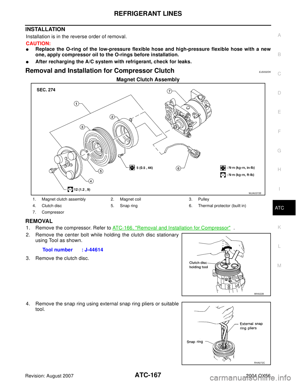
Removal and Installation for Compressor ClutchEJS002DK
Magnet Clutch Assembly
REMOVAL
1. Remove the compressor. Refer to ATC-166, "Removal and Installation for Compressor" .
2. Remove the center bolt while holding the clutch disc stationary
using Tool as shown.
3. Remove the clutch disc.
4. Remove the snap ring using external snap ring pliers or suitable
tool.
WJIA0372E
1. Magnet clutch assembly 2. Magnet coil 3. Pulley
4. Clutch disc 5. Snap ring 6. Thermal protector (built in)
7. Compressor
Tool number : J-44614
WHA228
RHA072C
Page 573 of 3371

ATC-168
REFRIGERANT LINES
Revision: August 20072004 QX56
5. Remove the pulley using Tool with a small adapter. Position the
small adapter on the end of the drive shaft and the center of the
puller on the small adapter.
CAUTION:
To prevent deformation of the pulley groove, the puller
claws should be hooked under the pulley groove and not
into the pulley groove.
6. Remove the magnet coil harness clip using a screwdriver,
remove the three magnet coil fixing screws and remove the
magnet coil.
INSPECTION
Clutch Disc
If the contact surface shows signs of damage due to excessive heat,
replace clutch disc and pulley.
Pulley
Check the appearance of the pulley assembly. If contact surface of pulley shows signs of excessive grooving,
replace clutch disc and pulley. The contact surfaces of the pulley assembly should be cleaned with a suitable
solvent before reinstallation.
Coil
Check magnet coil for loose connections or any cracked insulation.
INSTALLATION
1. Install the magnet coil.
CAUTION:
Be sure to align the magnet coil pin with the hole in the
compressor front head.
LHA173
WHA212
WHA183
WHA213
\"*2ATC-53, \"A/C")