Page 594 of 3371

AUDIO
AV-7
C
D
E
F
G
H
I
J
L
MA
B
AV
Revision: August 20072004 QX56
System DescriptionEKS007KA
Refer to Owner's Manual for audio system operating instructions.
Power is supplied at all times
�through 15A fuse [No. 17, located in the fuse block (J/B)]
�to subwoofer terminal 6
�through 20A fuse [No. 31, located in the fuse and fusible link box]
�to audio unit terminal 6
�to BOSE speaker amp. terminal 1
�to AV switch terminal 1 and
�to display control unit terminal 1.
With the ignition switch in the ACC or ON position, power is supplied
�through 10A fuse [No. 4, located in the fuse block (J/B)]
�to audio unit terminal 10 and
�to AV switch terminal 2 and
�to display control unit terminal 10.
With the ignition switch in the ON or START position, power is supplied
�through 10A fuse [No. 12, located in the fuse block (J/B)]
�to display control unit terminal 12.
Ground is supplied through the case of the audio unit.
Ground is also supplied
�to subwoofer terminal 5
�through body grounds B7 and B19 and
�to BOSE speaker amp. terminal 17
�to AV switch terminal 5 and
�to display unit terminal 1 and
�to display control unit terminal 3
�through body grounds M57, M61 and M79.
Then audio signals are supplied
�through audio unit terminals 1, 2, 3, 4, 13, 14, 15 and 16
�to BOSE speaker amp. terminals 23, 24, 25, 26, 27, 28, 29 and 30.
Audio signals are amplified by the BOSE speaker amp.
The amplified audio signals are supplied
�through BOSE speaker amp. terminals 2, 3, 9,10,11,12, 13, 14, 15, 16, 18 and 19
�to terminals + and - of front door speaker LH and RH and
�to terminals + and - of front tweeter LH and RH and
�to terminals + and - of center speaker and
�to terminals + and - of rear door speaker LH and RH and
�to terminals + and - of rear door tweeter LH and RH and
�to terminals 1 and 2 of subwoofer.
When one of steering wheel audio control switches is pushed, the resistance in steering switch circuit changes
depending on which button is pushed.
REAR AUDIO REMOTE CONTROL UNIT
Power is supplied
�from audio unit terminal 32
�to rear audio remote control unit terminal 13.
Ground is supplied
�to rear audio remote control unit terminal 15
�through body grounds B117 and B132.
Audio signals are supplied
Page 595 of 3371
AV-8
AUDIO
Revision: August 20072004 QX56
�through audio unit terminals 26, 27, 28 and 29
�to terminals 1, 2, 3, and 4 of rear audio remote control unit.
SATELLITE RADIO TUNER (PRE-WIRING)
The satellite radio tuner pre-wiring allows connection of a satellite radio tuner.
Power is supplied at all times
�through 20A fuse [No. 31, located in the fuse and fusible link box]
�to satellite radio tuner pre-wiring terminal 32.
With the ignition switch in the ACC or ON position, power is supplied
�through 10A fuse [No. 4, located in the fuse block (J/B)]
�to satellite radio tuner pre-wiring terminal 36.
Ground is supplied through the case of the satellite radio tuner.
SPEED SENSITIVE VOLUME SYSTEM
Volume level of this system goes up and down automatically in proportion to the vehicle speed. The control
level can be selected by the customer. Refer to Owner's Manual for operating instructions.
Page 616 of 3371

AUDIO
AV-29
C
D
E
F
G
H
I
J
L
MA
B
AV
Revision: August 20072004 QX56
FOR RADIO ONLY
NOTE:
1. The following noise results from variations in field strength, such as fading noise and multi-path noise, or
external noise from trains and other sources. It is not a malfunction.
�Fading noise: This noise occurs because of variations in the field strength in a narrow range due to moun-
tains or buildings blocking the signal.
�Multi-path noise: This noise results from the waves sent directly from the broadcast station arriving at the
antenna at a different time from the waves which reflect off mountains or buildings.
Symptom Possible cause
No sound
�Audio unit
�Antenna feeder, wiring or connections
�Antenna amplifier, power supply, wiring or connections
Noisy
�Audio unit
�Audio unit case ground
�Antenna feeder, wiring or connections
�Antenna amplifier, power supply, wiring or connections
�Noise prevention parts
�Each electrical equipment
�Wire harness of each piece of electrical equipment
All radio stations stored in memory are deleted
�Audio unit power circuit check. Refer to AV- 3 0 , "Power Supply Cir-
cuit Inspection" .
�Audio unit
Page 635 of 3371
AV-48
AUDIO ANTENNA
Revision: August 20072004 QX56
AUDIO ANTENNAPFP:28200
System DescriptionEKS007L6
With the ignition switch in ACC or ON, power is supplied
�through 10A fuse [No. 4, located in the fuse block (J/B)]
�to audio unit terminal 10.
Ground is supplied through the case of the antenna amp.
When the radio switch is turned ON, antenna signal is supplied
�through audio unit terminal 5
�to the antenna amp. terminal 1.
Then the antenna amp. is activated.
The amplified radio signals are supplied to the audio unit through the antenna amp.
Page 640 of 3371
DVD ENTERTAINMENT SYSTEM
AV-53
C
D
E
F
G
H
I
J
L
MA
B
AV
Revision: August 20072004 QX56
System DescriptionEKS007LB
Refer to Owner's Manual for DVD entertainment system operating instructions.
Power is supplied at all times
�through 20A fuse (No. 31, located in the fuse and fusible link box)
�to DVD player terminal 16.
With the ignition switch in the ACC or ON position, power is supplied
�through 10A fuse [No. 4, located in the fuse block (J/B)]
�to DVD player terminal 15.
Power is also supplied
�from DVD player terminals 31 and 32
�to video monitor terminals 11 and 12.
Ground is supplied
�to DVD player terminal 22
�through body grounds M57, M61 and M79.
Audio signals are supplied
�through DVD player terminals 1, 2, 3 and 4
�to audio unit terminals 34, 35, 36 and 37.
Video signals are supplied
�through DVD player terminals 23, 24, 28 and 29
�to video monitor terminals 5, 6, 7 and 8.
Page 655 of 3371

AV-68
NAVIGATION SYSTEM
Revision: August 20072004 QX56
Setting of the under section display
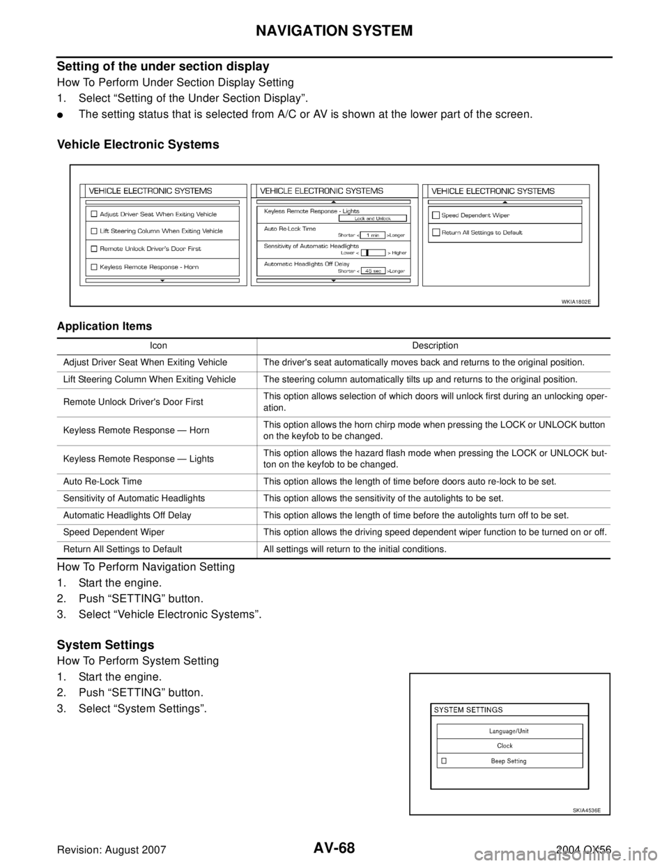
How To Perform Under Section Display Setting
1. Select “Setting of the Under Section Display”.
�The setting status that is selected from A/C or AV is shown at the lower part of the screen.
Vehicle Electronic Systems
Application Items
How To Perform Navigation Setting
1. Start the engine.
2. Push “SETTING” button.
3. Select “Vehicle Electronic Systems”.
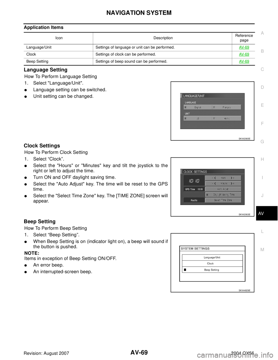
System Settings
How To Perform System Setting
1. Start the engine.
2. Push “SETTING” button.
3. Select “System Settings”.
Icon Description
Adjust Driver Seat When Exiting Vehicle The driver's seat automatically moves back and returns to the original position.
Lift Steering Column When Exiting Vehicle The steering column automatically tilts up and returns to the original position.
Remote Unlock Driver's Door FirstThis option allows selection of which doors will unlock first during an unlocking oper-
ation.
Keyless Remote Response — HornThis option allows the horn chirp mode when pressing the LOCK or UNLOCK button
on the keyfob to be changed.
Keyless Remote Response — LightsThis option allows the hazard flash mode when pressing the LOCK or UNLOCK but-
ton on the keyfob to be changed.
Auto Re-Lock Time This option allows the length of time before doors auto re-lock to be set.
Sensitivity of Automatic Headlights This option allows the sensitivity of the autolights to be set.
Automatic Headlights Off Delay This option allows the length of time before the autolights turn off to be set.
Speed Dependent Wiper This option allows the driving speed dependent wiper function to be turned on or off.
Return All Settings to Default All settings will return to the initial conditions.
WKIA1802E
SKIA4536E
Page 656 of 3371

NAVIGATION SYSTEM
AV-69
C
D
E
F
G
H
I
J
L
MA
B
AV
Revision: August 20072004 QX56
Application Items
Language Setting
How To Perform Language Setting
1. Select "Language/Unit".
�Language setting can be switched.
�Unit setting can be changed.
Clock Settings
How To Perform Clock Setting
1. Select “Clock”.
�Select the "Hours" or "Minutes" key and tilt the joystick to the
right or left to adjust the time.
�Turn ON and OFF daylight saving time.
�Select the "Auto Adjust" key. The time will be reset to the GPS
time.
�Select the "Select Time Zone" key. The [TIME ZONE] screen will
appear.
Beep Setting
How To Perform Beep Setting
1. Select “Beep Setting”.
�When Beep Setting is on (indicator light on), a beep will sound if
the button is pushed.
NOTE:
Items in exception of Beep Setting ON/OFF.
�An error beep.
�An interrupted-screen beep.
Icon DescriptionReference
page
Language/Unit Settings of language or unit can be performed.AV- 6 9
Clock Settings of clock can be performed.AV- 6 9
Beep Setting Settings of beep sound can be performed.AV- 6 9
SKIA2065E
SKIA2063E
SKIA4829E
Page 663 of 3371

AV-76
NAVIGATION SYSTEM
Revision: August 20072004 QX56
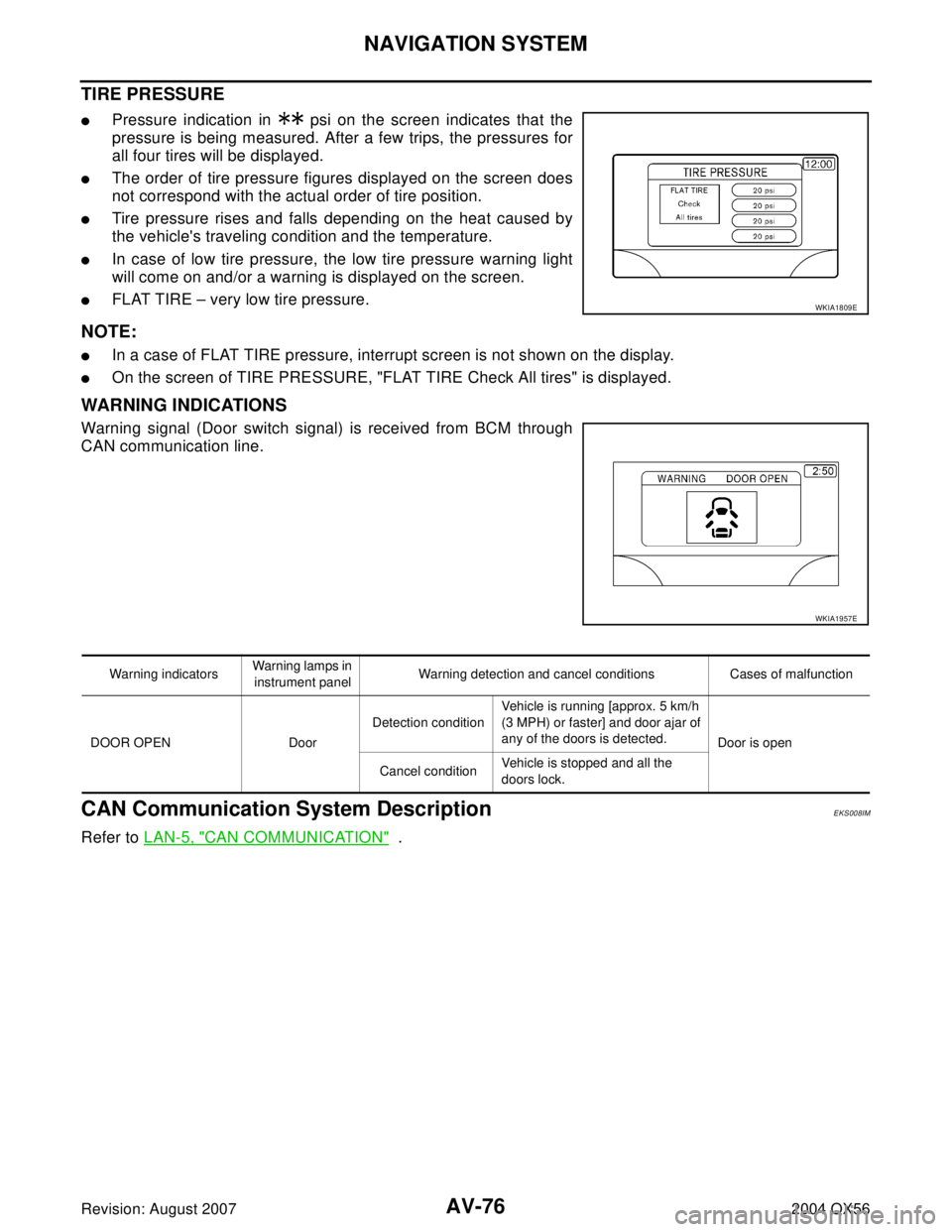
TIRE PRESSURE
�Pressure indication in psi on the screen indicates that the
pressure is being measured. After a few trips, the pressures for
all four tires will be displayed.
�The order of tire pressure figures displayed on the screen does
not correspond with the actual order of tire position.
�Tire pressure rises and falls depending on the heat caused by
the vehicle's traveling condition and the temperature.
�In case of low tire pressure, the low tire pressure warning light
will come on and/or a warning is displayed on the screen.
�FLAT TIRE – very low tire pressure.
NOTE:
�In a case of FLAT TIRE pressure, interrupt screen is not shown on the display.
�On the screen of TIRE PRESSURE, "FLAT TIRE Check All tires" is displayed.
WARNING INDICATIONS
Warning signal (Door switch signal) is received from BCM through
CAN communication line.
CAN Communication System DescriptionEKS008IM
Refer to LAN-5, "CAN COMMUNICATION" .
WKIA1809E
WKIA1957E
Warning indicatorsWarning lamps in
instrument panelWarning detection and cancel conditions Cases of malfunction
DOOR OPEN DoorDetection conditionVehicle is running [approx. 5 km/h
(3 MPH) or faster] and door ajar of
any of the doors is detected.
Door is open
Cancel conditionVehicle is stopped and all the
doors lock.