Page 2677 of 3371

Revision: August 20072004 QX56
IPDM E/R STATUS CONTROL
In order to save power, IPDM E/R switches status automatically based on each o")
PG-18
IPDM E/R (INTELLIGENT POWER DISTRIBUTION MODULE ENGINE ROOM)
Revision: August 20072004 QX56
IPDM E/R STATUS CONTROL
In order to save power, IPDM E/R switches status automatically based on each operating condition.
1. CAN communication status
�CAN communication is normally performed with other control units.
�Individual unit control by IPDM E/R is normally performed.
�When sleep request signal is received from BCM, mode is switched to sleep waiting status.
2. Sleep waiting status
�Process to stop CAN communication is activated.
�All systems controlled by IPDM E/R are stopped. When 1 second has elapsed after CAN communica-
tion with other control units is stopped, mode switches to sleep status.
3. Sleep status
�IPDM E/R operates in low current-consumption mode.
�CAN communication is stopped.
�When a change in CAN communication signal is detected, mode switches to CAN communication sta-
tus.
�When a change in ignition switch signal is detected, mode switches to CAN communication status.
CAN Communication System DescriptionEKS007NO
Refer to LAN-5, "CAN COMMUNICATION" .
Function of Detecting Ignition Relay MalfunctionEKS007NP
�When the integrated ignition relay is stuck in a "closed contact" position and cannot be turned OFF, IPDM
E/R turns ON tail and parking lamps for 10 minutes to indicate IPDM E/R malfunction.
�When the state of the integrated ignition relay does not agree with the state of the ignition switch signal
received via CAN communication, the IPDM E/R activates the tail lamp relay.
NOTE:
When the ignition switch is turned ON, the tail lamps are OFF.
A/C compressor A/C compressor OFF
Front fog lamps Front fog lamp relay OFFControlled system Fail-safe mode
Ignition switch signal Ignition relay status Tail lamp relay
ON ON —
OFF OFF —
ON OFF —
OFF ON ON (10 minutes)
Page 2678 of 3371

PG-19
C
D
E
F
G
H
I
J
L
MA
B
PG
Revision: August 20072004 QX56
CONSULT-II Function (IPDM E/R)EKS007NQ
CONSULT-II can display each diagnosti")
IPDM E/R (INTELLIGENT POWER DISTRIBUTION MODULE ENGINE ROOM)
PG-19
C
D
E
F
G
H
I
J
L
MA
B
PG
Revision: August 20072004 QX56
CONSULT-II Function (IPDM E/R)EKS007NQ
CONSULT-II can display each diagnostic item using the diagnostic test modes shown following.
CONSULT-II BASIC OPERATION
CAUTION:
If CONSULT-II is used with no connection of CONSULT-II CONVERTER, malfunctions might be
detected in self-diagnosis depending on control unit which carries out CAN communication.
1. With the ignition switch OFF, connect CONSULT-II and CON-
SULT-II CONVERTER to the data link connector, then turn igni-
tion switch ON.
2. Touch “START (NISSAN BASED VHCL)”.
3. Touch “IPDM E/R” on “SELECT SYSTEM” screen.
�If “IPDM E/R” is not displayed, print "SELECT SYSTEM"
screen, then refer to GI-39, "
CONSULT-II Data Link Connec-
tor (DLC) Circuit" .
IPDM E/R diagnostic mode Description
SELF-DIAG RESULTS Displays IPDM E/R self-diagnosis results.
DATA MONITOR Displays IPDM E/R input/output data in real time.
CAN DIAG SUPPORT MNTR The result of transmit/receive diagnosis of CAN communication can be read.
ACTIVE TEST Operation of electrical loads can be checked by sending drive signal to them.
BBIA0369E
BCIA0029E
BCIA0030E
Page 2681 of 3371

Revision: August 20072004 QX56
All Signals, Main Signals, Selection From Menu
NOTE:
Perform monitoring of IPDM E/R data with the igni")
PG-22
IPDM E/R (INTELLIGENT POWER DISTRIBUTION MODULE ENGINE ROOM)
Revision: August 20072004 QX56
All Signals, Main Signals, Selection From Menu
NOTE:
Perform monitoring of IPDM E/R data with the ignition switch ON. When the ignition switch is in ACC position,
display may not be correct.
ACTIVE TEST
Operation Procedure
1. Touch “ACTIVE TEST” on “SELECT DIAG-MODE” screen.
2. Touch item to be tested, and check operation.
3. Touch “START”.
4. Touch "STOP" while testing to stop the operation.
Item nameCONSULT-II
screen displayDisplay or unitMonitor item selection
Description
ALL
SIGNALSMAIN
SIGNALSSELECTION
FROM MENU
Motor fan requestMOTOR FAN
REQ1/2/3/4 X X X Signal status input from ECM
Compressor request AC COMP REQ ON/OFF X X X Signal status input from ECM
Position lights
requestTAIL & CLR REQ ON/OFF X X X Signal status input from BCM
Headlamp low beam
requestHL LO REQ ON/OFF X X X Signal status input from BCM
Headlamp high
beam requestHL HI REQ ON/OFF X X X Signal status input from BCM
Front fog lghts
requestFR FOG REQ ON/OFF X X X Signal status input from BCM
Front wiper request FR WIP REQSTOP/1LOW/
LOW/HIX X X Signal status input from BCM
Wiper auto stopWIP AUTO
STOPACT P/STOP P X X X Output status of IPDM E/R
Wiper protection WIP PROT OFF/Block X X X Control status of IPDM E/R
Starter request ST RLY REQ ON/OFF X X
Status of input signal
NOTE
Ignition relay
statusIGN RLY ON/OFF X X XIgnition relay status monitored
with IPDM E/R
Rear defogger
requestRR DEF REQ ON/OFF X X X Signal status input from BCM
Oil pressure switch OIL P SW OPEN/CLOSE X XSignal status input from IPDM
E/R (function is not enabled)
Hood switch HOOD SW OFF XSignal status input from IPDM
E/R (function is not enabled)
Theft warning horn
requestTHFT HRN REQ ON/OFF X X Signal status input from BCM
Horn chirp HORN CHIRP ON/OFF X X Output status of IPDM E/R
Daytime running
lamp requestDTRL REQ ON/OFF X X Signal status input from BCM
Test name CONSULT-II screen display Description
Rear defogger output REAR DEFOGGERWith a certain ON-OFF operation, the rear defogger relay can be oper-
ated.
Front wiper (HI, LO) output FRONT WIPERWith a certain operation (OFF, HI, LO), the front wiper relay (Lo, Hi)
can be operated.
Cooling fan output MOTOR FAN With a certain operation (1, 2, 3, 4), the cooling fan can be operated.
Lamp (HI, LO, TAIL, FOG)
outputEXTERNAL LAMPSWith a certain operation (OFF, TAIL, LO, HI, FOG), the lamp relay
(Low, High, Tail, Fog) can be operated.
Page 2682 of 3371

PG-23
C
D
E
F
G
H
I
J
L
MA
B
PG
Revision: August 20072004 QX56
Auto Active TestEKS007NR
DESCRIPTION
�In auto active test mode, operation in")
IPDM E/R (INTELLIGENT POWER DISTRIBUTION MODULE ENGINE ROOM)
PG-23
C
D
E
F
G
H
I
J
L
MA
B
PG
Revision: August 20072004 QX56
Auto Active TestEKS007NR
DESCRIPTION
�In auto active test mode, operation inspection can be performed when IPDM E/R sends a drive signal to
the following systems:
–Rear window defogger
–Front wipers
–Tail and parking lamps
–Front fog lamps
–Headlamps (Hi, Lo)
–A/C compressor (magnet clutch)
–Cooling fan
OPERATION PROCEDURE
1. Close hood and front door RH, and lift wiper arms away from windshield (to prevent glass damage by
wiper operation).
NOTE:
When auto active test is performed with hood opened, sprinkle water on windshield beforehand.
2. Turn ignition switch OFF.
3. Turn ignition switch ON and, within 20 seconds, press front door switch LH 10 times. Then turn ignition
switch OFF.
4. Turn ignition switch ON within 10 seconds after ignition switch OFF.
5. When auto active test mode is actuated, horn chirps once.
6. After a series of operations is repeated three times, auto active test is completed.
NOTE:
When auto active test mode has to be cancelled halfway, turn ignition switch OFF.
CAUTION:
Be sure to perform BL-93, "
Door Switch Check" when the auto active test cannot be performed.
INSPECTION IN AUTO ACTIVE TEST MODE
�When auto active test mode is actuated, the following seven steps are repeated three times.
Cornering lamp output CORNERING LAMP —
Horn output HORN With a certain ON-OFF operation, the horn relay can be operated.Test name CONSULT-II screen display Description
WKIA1972E
Page 2721 of 3371

PG-62
HARNESS
Revision: August 20072004 QX56
HSEAT SE Heated Seat
IATS EC Intake Air Temperature Sensor
ICC ACS Intelligent Cruise Control
ICCBOF EC ICC Brake Switch
ICC/BS EC ICC Steering Switch
ICC/SW EC ICC Brake Switch
I/MIRR GW Inside Mirror (Auto Anti-Dazzling Mirror)
IGNSYS EC Ignition System
ILL LT Illumination
INJECT EC Injector
INT/L LT Room/Map, Vanity, Cargo, Personal, Foot, Step, and Puddle Lamps
KEYLES BL Remote Keyless Entry System
KS EC Knock Sensor
MAFS EC Mass Air Flow Sensor
MAIN EC Main Power Supply and Ground Circuit
METER DI Speedometer, Tachometer, Temp. and Fuel Gauges
MIL/DL EC Malfunction Indicator Lamp
MIRROR GW Door Mirror
NATS BL Nissan Anti-Theft System
NAVI AV Navigation System
O2H2B1 EC Rear Heated Oxygen Sensor 2 Heater Bank 1
O2H2B2 EC Rear Heated Oxygen Sensor 2 Heater Bank 2
O2S2B1 EC Heated Oxygen Sensor 2 Bank 1
O2S2B2 EC Heated Oxygen Sensor 2 Bank 2
P/SCKT WW Power Socket
PGC/V EC EVAP Canister Purge Volume Control Solenoid Valve
PHASE EC Camshaft Position Sensor (PHASE) (Bank 1)
PNP/SW EC Park/Neutral Position Switch
POS EC Crankshaft Position Sensor (POS)
POWER PG Power Supply Routing
PRE/SE EC EVAP Control System Pressure Sensor
PS/SEN EC Power Steering Pressure Sensor
R/VIEW DI Rear View Monitor
RP/SEN EC Refrigerant Pressure Sensor
SEAT SE Power Seat (Without Memory)
SEN/PW EC Sensor Power Supply
SHIFT AT A/T Shift Lock System
SONAR DI Rear Sonar System
SROOF RF Sunroof
SRS SRS Supplemental Restraint System
START SC Starting System
STOP/L LT Stop Lamp
T/TOW LT Trailer Tow
T/WARN WT Low Tire Pressure Warning System
TAIL/L LT Parking, License and Tail Lamps
T/F TF Transfer Case
TPS1 EC Throttle Position Sensor
TPS2 EC Throttle Position Sensor
TPS3 EC Throttle Position Sensor
TRNSCV BL HOMELINK® Universal Transceiver
TURN LT Turn Signal and Hazard Warning Lamps
VDC BRC Vehicle Dynamic Control System
Page 2761 of 3371
PS-10
STEERING COLUMN
Revision: August 20072004 QX56
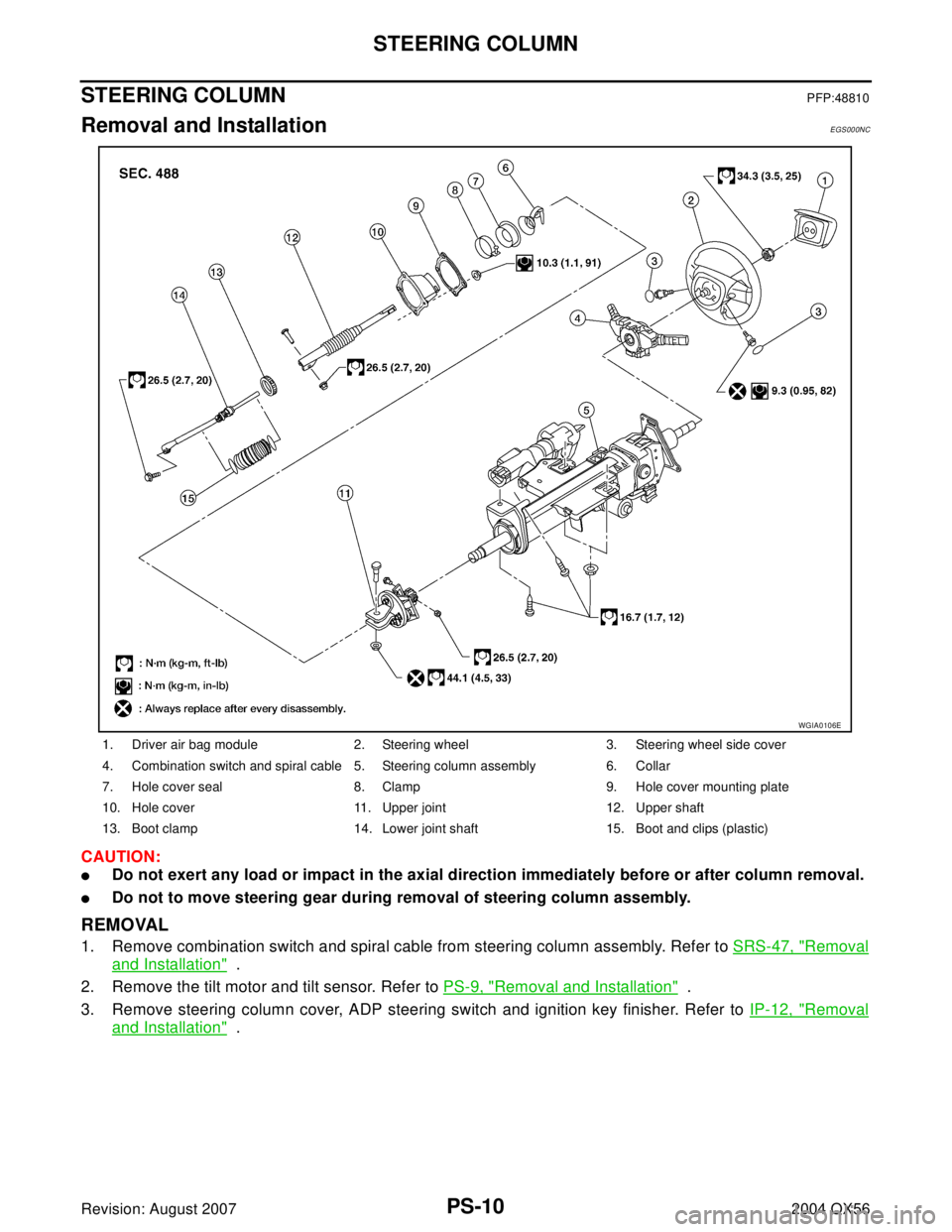
STEERING COLUMNPFP:48810
Removal and InstallationEGS000NC
CAUTION:
�Do not exert any load or impact in the axial direction immediately before or after column removal.
�Do not to move steering gear during removal of steering column assembly.
REMOVAL
1. Remove combination switch and spiral cable from steering column assembly. Refer to SRS-47, "Removal
and Installation" .
2. Remove the tilt motor and tilt sensor. Refer to PS-9, "
Removal and Installation" .
3. Remove steering column cover, ADP steering switch and ignition key finisher. Refer to IP-12, "
Removal
and Installation" .
1. Driver air bag module 2. Steering wheel 3. Steering wheel side cover
4. Combination switch and spiral cable 5. Steering column assembly 6. Collar
7. Hole cover seal 8. Clamp 9. Hole cover mounting plate
10. Hole cover 11. Upper joint 12. Upper shaft
13. Boot clamp 14. Lower joint shaft 15. Boot and clips (plastic)
WGIA0106E
Page 2764 of 3371
STEERING COLUMN
PS-13
C
D
E
F
H
I
J
K
L
MA
B
PS
Revision: August 20072004 QX56
Disassembly and AssemblyEGS000ND
DISASSEMBLY
1. Remove mounting bolt from upper joint, then remove upper joint from steering column assembly.
2. Remove ignition switch tamper resistant self-shear screws with a drill or other suitable tool.
1. Steering column assembly 2. Upper joint 3. Ignition switch
4. Tamper resistant self-shear screw
WGIA0091E
Page 2811 of 3371
RF-10
SUNROOF
Revision: August 20072004 QX56
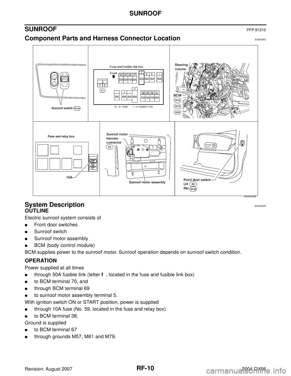
SUNROOFPFP:91210
Component Parts and Harness Connector LocationEIS002WJ
System DescriptionEIS002WK
OUTLINE
Electric sunroof system consists of
�Front door switches
�Sunroof switch
�Sunroof motor assembly
�BCM (body control module)
BCM supplies power to the sunroof motor. Sunroof operation depends on sunroof switch condition.
OPERATION
Power supplied at all times
�through 50A fusible link (letter f , located in the fuse and fusible link box)
�to BCM terminal 70, and
�through BCM terminal 69
�to sunroof motor assembly terminal 5.
With ignition switch ON or START position, power is supplied
�through 10A fuse (No. 59, located in the fuse and relay box)
�to BCM terminal 38.
Ground is supplied
�to BCM terminal 67
�through grounds M57, M61 and M79.
WIIA0545E