Page 1661 of 3371
EC-470Revision: August 2007
DTC P1276, P1286 A/F SENSOR 1
2004 QX56
2. CHECK AIR FUEL RATIO (A/F) SENSOR 1 POWER SUPPLY CIRCUIT
1. Disconnect A/F sensor 1 harness connector.
2. Turn ignition switch ON.
3. Check voltage between A/F sensor 1 terminal 3 and ground with
CONSULT-II or tester.
OK or NG
OK >> GO TO 4.
NG >> GO TO 3.
3. DETECT MALFUNCTIONING PART
Check the following.
�Harness connectors E5, F14
�IPDM E/R harness connector E119
�10A fuse
�Harness for open or short between A/F sensor 1 and fuse
>> Repair or replace harness or connectors. Voltage: Battery voltage
BBIA0376E
PBIB1683E
Page 1663 of 3371
EC-472Revision: August 2007
DTC P1278, P1288 A/F SENSOR 1
2004 QX56
DTC P1278, P1288 A/F SENSOR 1PFP:22693
Component DescriptionUBS00HAF
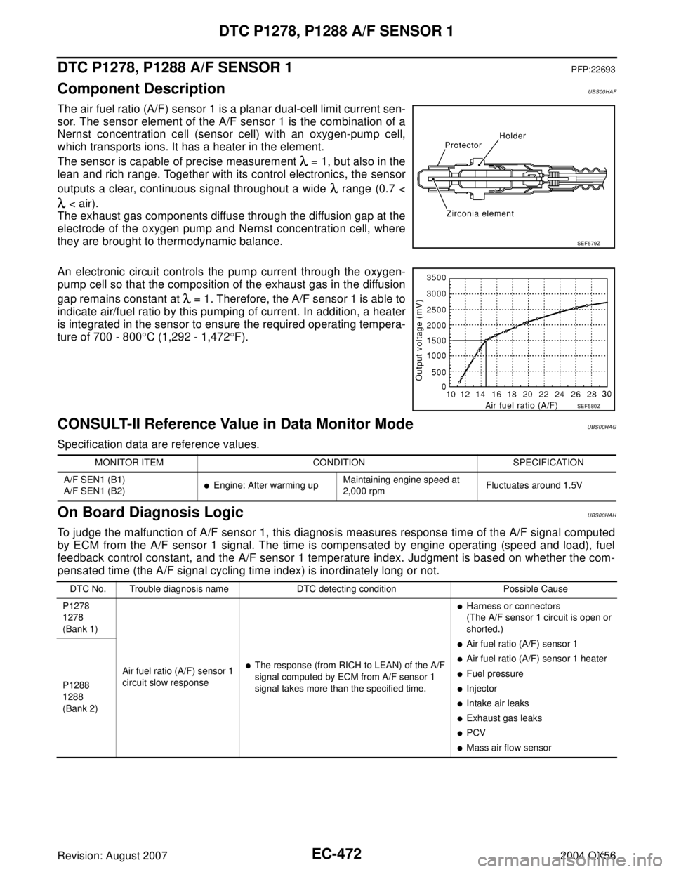
The air fuel ratio (A/F) sensor 1 is a planar dual-cell limit current sen-
sor. The sensor element of the A/F sensor 1 is the combination of a
Nernst concentration cell (sensor cell) with an oxygen-pump cell,
which transports ions. It has a heater in the element.
The sensor is capable of precise measurement = 1, but also in the
lean and rich range. Together with its control electronics, the sensor
outputs a clear, continuous signal throughout a wide range (0.7 <
< air).
The exhaust gas components diffuse through the diffusion gap at the
electrode of the oxygen pump and Nernst concentration cell, where
they are brought to thermodynamic balance.
An electronic circuit controls the pump current through the oxygen-
pump cell so that the composition of the exhaust gas in the diffusion
gap remains constant at = 1. Therefore, the A/F sensor 1 is able to
indicate air/fuel ratio by this pumping of current. In addition, a heater
is integrated in the sensor to ensure the required operating tempera-
ture of 700 - 800°C (1,292 - 1,472°F).
CONSULT-II Reference Value in Data Monitor ModeUBS00HAG
Specification data are reference values.
On Board Diagnosis LogicUBS00HAH
To judge the malfunction of A/F sensor 1, this diagnosis measures response time of the A/F signal computed
by ECM from the A/F sensor 1 signal. The time is compensated by engine operating (speed and load), fuel
feedback control constant, and the A/F sensor 1 temperature index. Judgment is based on whether the com-
pensated time (the A/F signal cycling time index) is inordinately long or not.
SEF 5 79 Z
SEF 5 80 Z
MONITOR ITEM CONDITION SPECIFICATION
A/F SEN1 (B1)
A/F SEN1 (B2)
�Engine: After warming upMaintaining engine speed at
2,000 rpm Fluctuates around 1.5V
DTC No. Trouble diagnosis name DTC detecting condition Possible Cause
P1278
1278
(Bank 1)
Air fuel ratio (A/F) sensor 1
circuit slow response
�The response (from RICH to LEAN) of the A/F
signal computed by ECM from A/F sensor 1
signal takes more than the specified time.
�Harness or connectors
(The A/F sensor 1 circuit is open or
shorted.)
�Air fuel ratio (A/F) sensor 1
�Air fuel ratio (A/F) sensor 1 heater
�Fuel pressure
�Injector
�Intake air leaks
�Exhaust gas leaks
�PCV
�Mass air flow sensor P1288
1288
(Bank 2)
Page 1672 of 3371
DTC P1278, P1288 A/F SENSOR 1
EC-481
C
D
E
F
G
H
I
J
K
L
MA
EC
Revision: August 20072004 QX56
6. CHECK A/F SENSOR 1 POWER SUPPLY CIRCUIT
1. Turn ignition switch OFF.
2. Disconnect A/F sensor 1 harness connector.
3. Turn ignition switch ON.
4. Check voltage between A/F sensor 1 terminal 3 and ground with
CONSULT-II or tester.
OK or NG
OK >> GO TO 8.
NG >> GO TO 7.
7. DETECT MALFUNCTIONING PART
Check the following.
�Harness connectors E5, F14
�IPDM E/R harness connector E119
�10A fuse
�Harness for open or short between A/F sensor 1 and fuse
>> Repair or replace harness or connectors. Voltage: Battery voltage
BBIA0376E
PBIB1683E
Page 1675 of 3371
EC-484Revision: August 2007
DTC P1279, P1289 A/F SENSOR 1
2004 QX56
DTC P1279, P1289 A/F SENSOR 1PFP:22693
Component DescriptionUBS00HAM
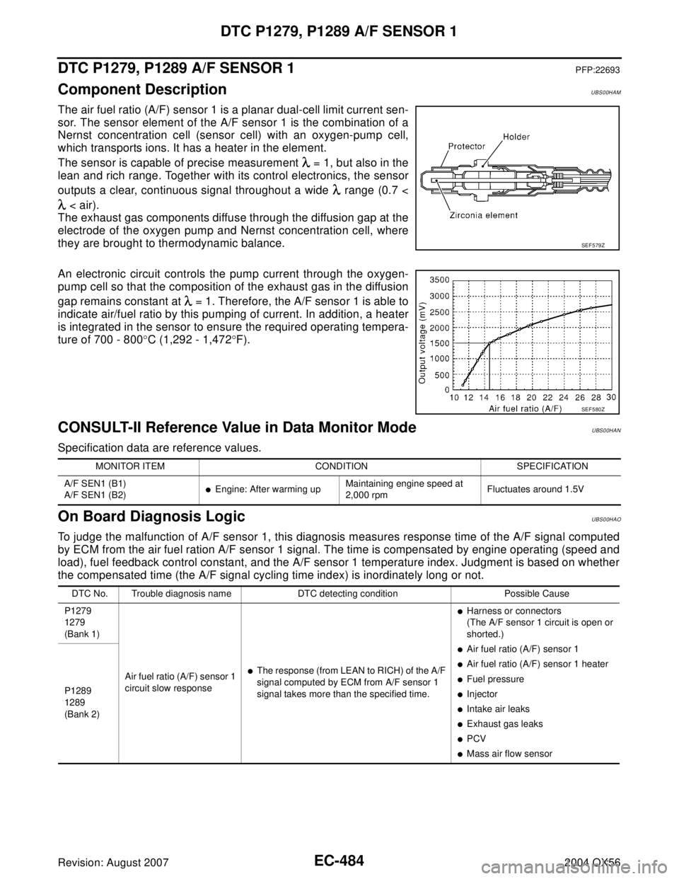
The air fuel ratio (A/F) sensor 1 is a planar dual-cell limit current sen-
sor. The sensor element of the A/F sensor 1 is the combination of a
Nernst concentration cell (sensor cell) with an oxygen-pump cell,
which transports ions. It has a heater in the element.
The sensor is capable of precise measurement = 1, but also in the
lean and rich range. Together with its control electronics, the sensor
outputs a clear, continuous signal throughout a wide range (0.7 <
< air).
The exhaust gas components diffuse through the diffusion gap at the
electrode of the oxygen pump and Nernst concentration cell, where
they are brought to thermodynamic balance.
An electronic circuit controls the pump current through the oxygen-
pump cell so that the composition of the exhaust gas in the diffusion
gap remains constant at = 1. Therefore, the A/F sensor 1 is able to
indicate air/fuel ratio by this pumping of current. In addition, a heater
is integrated in the sensor to ensure the required operating tempera-
ture of 700 - 800°C (1,292 - 1,472°F).
CONSULT-II Reference Value in Data Monitor ModeUBS00HAN
Specification data are reference values.
On Board Diagnosis LogicUBS00HAO
To judge the malfunction of A/F sensor 1, this diagnosis measures response time of the A/F signal computed
by ECM from the air fuel ration A/F sensor 1 signal. The time is compensated by engine operating (speed and
load), fuel feedback control constant, and the A/F sensor 1 temperature index. Judgment is based on whether
the compensated time (the A/F signal cycling time index) is inordinately long or not.
SEF 5 79 Z
SEF 5 80 Z
MONITOR ITEM CONDITION SPECIFICATION
A/F SEN1 (B1)
A/F SEN1 (B2)
�Engine: After warming upMaintaining engine speed at
2,000 rpmFluctuates around 1.5V
DTC No. Trouble diagnosis name DTC detecting condition Possible Cause
P1279
1279
(Bank 1)
Air fuel ratio (A/F) sensor 1
circuit slow response
�The response (from LEAN to RICH) of the A/F
signal computed by ECM from A/F sensor 1
signal takes more than the specified time.
�Harness or connectors
(The A/F sensor 1 circuit is open or
shorted.)
�Air fuel ratio (A/F) sensor 1
�Air fuel ratio (A/F) sensor 1 heater
�Fuel pressure
�Injector
�Intake air leaks
�Exhaust gas leaks
�PCV
�Mass air flow sensor P1289
1289
(Bank 2)
Page 1684 of 3371
DTC P1279, P1289 A/F SENSOR 1
EC-493
C
D
E
F
G
H
I
J
K
L
MA
EC
Revision: August 20072004 QX56
6. CHECK A/F SENSOR 1 POWER SUPPLY CIRCUIT
1. Turn ignition switch OFF.
2. Disconnect A/F sensor 1 harness connector.
3. Turn ignition switch ON.
4. Check voltage between A/F sensor 1 terminal 3 and ground with
CONSULT-II or tester.
OK or NG
OK >> GO TO 8.
NG >> GO TO 7.
7. DETECT MALFUNCTIONING PART
Check the following.
�Harness connectors E5, F14
�IPDM E/R harness connector E119
�10A fuse
�Harness for open or short between A/F sensor 1 and fuse
>> Repair or replace harness or connectors. Voltage: Battery voltage
BBIA0376E
PBIB1683E
Page 1721 of 3371
EC-530Revision: August 2007
DTC P1572 ICC BRAKE SWITCH
2004 QX56
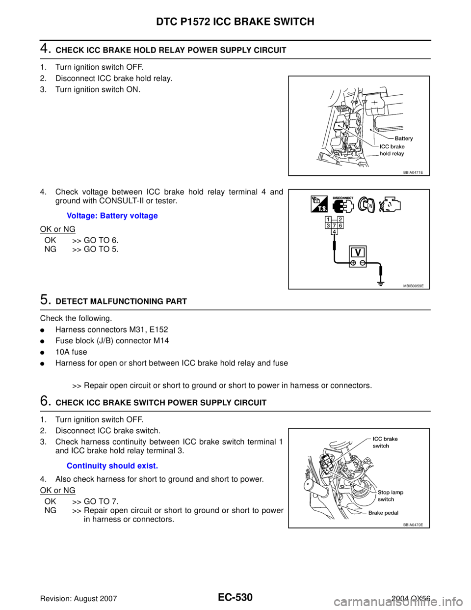
4. CHECK ICC BRAKE HOLD RELAY POWER SUPPLY CIRCUIT
1. Turn ignition switch OFF.
2. Disconnect ICC brake hold relay.
3. Turn ignition switch ON.
4. Check voltage between ICC brake hold relay terminal 4 and
ground with CONSULT-II or tester.
OK or NG
OK >> GO TO 6.
NG >> GO TO 5.
5. DETECT MALFUNCTIONING PART
Check the following.
�Harness connectors M31, E152
�Fuse block (J/B) connector M14
�10A fuse
�Harness for open or short between ICC brake hold relay and fuse
>> Repair open circuit or short to ground or short to power in harness or connectors.
6. CHECK ICC BRAKE SWITCH POWER SUPPLY CIRCUIT
1. Turn ignition switch OFF.
2. Disconnect ICC brake switch.
3. Check harness continuity between ICC brake switch terminal 1
and ICC brake hold relay terminal 3.
4. Also check harness for short to ground and short to power.
OK or NG
OK >> GO TO 7.
NG >> Repair open circuit or short to ground or short to power
in harness or connectors.
BBIA0471E
Voltage: Battery voltage
MBIB0059E
Continuity should exist.
BBIA0470E
Page 1723 of 3371
EC-532Revision: August 2007
DTC P1572 ICC BRAKE SWITCH
2004 QX56
11 . DETECT MALFUNCTIONING PART
Check the following.
�Harness connectors M31, E152
�Fuse block (J/B) connector M60
�10A fuse
�Harness for open or short between stop lamp switch and battery
>> Repair open circuit or short to ground or short to power in harness or connectors.
12. CHECK STOP LAMP SWITCH INPUT SIGNAL CIRCUIT FOR OPEN AND SHORT
1. Disconnect ECM harness connector.
2. Check harness continuity between ECM terminal 101 and stop lamp switch terminal 4.
Refer to Wiring Diagram.
3. Also check harness for short to ground and short to power.
OK or NG
OK >> GO TO 13.
NG >> Repair open circuit or short to ground or short to power in harness or connectors.
13. CHECK STOP LAMP SWITCH
Refer to EC-532, "
Component Inspection"
OK or NG
OK >> GO TO 14.
NG >> Replace stop lamp switch.
14. CHECK INTERMITTENT INCIDENT
Refer to EC-127, "
TROUBLE DIAGNOSIS FOR INTERMITTENT INCIDENT" .
>>INSPECTION END
Component InspectionUBS00HZ5
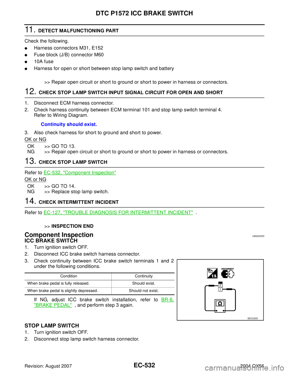
ICC BRAKE SWITCH
1. Turn ignition switch OFF.
2. Disconnect ICC brake switch harness connector.
3. Check continuity between ICC brake switch terminals 1 and 2
under the following conditions.
If NG, adjust ICC brake switch installation, refer to BR-6,
"BRAKE PEDAL" , and perform step 3 again.
STOP LAMP SWITCH
1. Turn ignition switch OFF.
2. Disconnect stop lamp switch harness connector.Continuity should exist.
Condition Continuity
When brake pedal is fully released. Should exist.
When brake pedal is slightly depressed. Should not exist.
SEC0 23 D
Page 1730 of 3371
DTC P1572 ASCD BRAKE SWITCH
EC-539
C
D
E
F
G
H
I
J
K
L
MA
EC
Revision: August 20072004 QX56
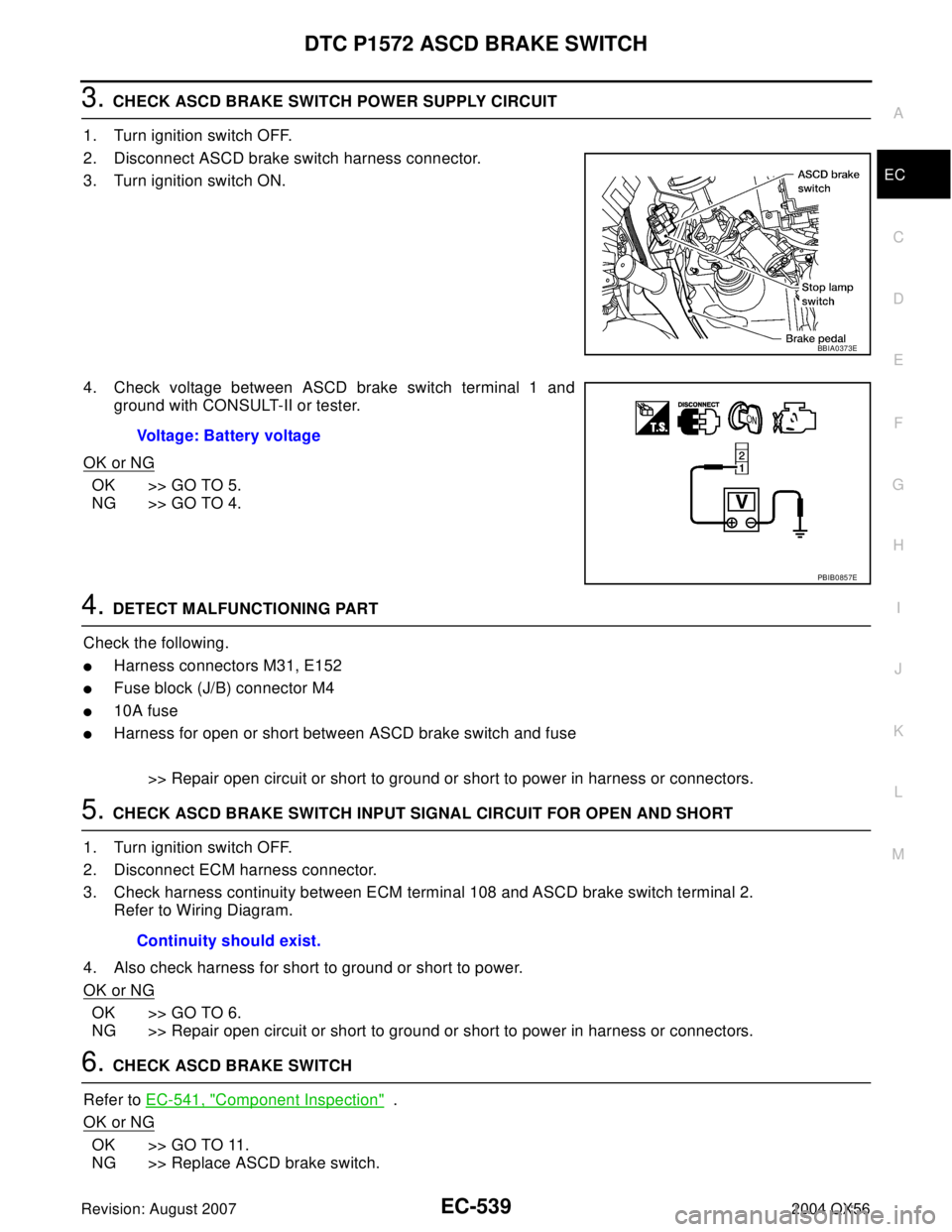
3. CHECK ASCD BRAKE SWITCH POWER SUPPLY CIRCUIT
1. Turn ignition switch OFF.
2. Disconnect ASCD brake switch harness connector.
3. Turn ignition switch ON.
4. Check voltage between ASCD brake switch terminal 1 and
ground with CONSULT-II or tester.
OK or NG
OK >> GO TO 5.
NG >> GO TO 4.
4. DETECT MALFUNCTIONING PART
Check the following.
�Harness connectors M31, E152
�Fuse block (J/B) connector M4
�10A fuse
�Harness for open or short between ASCD brake switch and fuse
>> Repair open circuit or short to ground or short to power in harness or connectors.
5. CHECK ASCD BRAKE SWITCH INPUT SIGNAL CIRCUIT FOR OPEN AND SHORT
1. Turn ignition switch OFF.
2. Disconnect ECM harness connector.
3. Check harness continuity between ECM terminal 108 and ASCD brake switch terminal 2.
Refer to Wiring Diagram.
4. Also check harness for short to ground or short to power.
OK or NG
OK >> GO TO 6.
NG >> Repair open circuit or short to ground or short to power in harness or connectors.
6. CHECK ASCD BRAKE SWITCH
Refer to EC-541, "
Component Inspection" .
OK or NG
OK >> GO TO 11.
NG >> Replace ASCD brake switch.
BBIA0373E
Voltage: Battery voltage
PBIB0857E
Continuity should exist.