Page 1321 of 3371
EC-130Revision: August 2007
POWER SUPPLY AND GROUND CIRCUIT
2004 QX56
4. DETECT MALFUNCTIONING PART
Check the following.
�10A fuse
�Harness for open or short between ECM and ignition switch
>> Repair harness or connectors.
5. CHECK GROUND CONNECTIONS
1. Turn ignition switch OFF.
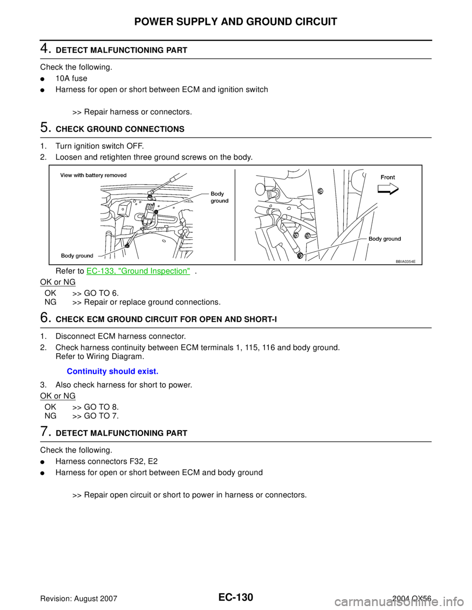
2. Loosen and retighten three ground screws on the body.
Refer to EC-133, "
Ground Inspection" .
OK or NG
OK >> GO TO 6.
NG >> Repair or replace ground connections.
6. CHECK ECM GROUND CIRCUIT FOR OPEN AND SHORT-I
1. Disconnect ECM harness connector.
2. Check harness continuity between ECM terminals 1, 115, 116 and body ground.
Refer to Wiring Diagram.
3. Also check harness for short to power.
OK or NG
OK >> GO TO 8.
NG >> GO TO 7.
7. DETECT MALFUNCTIONING PART
Check the following.
�Harness connectors F32, E2
�Harness for open or short between ECM and body ground
>> Repair open circuit or short to power in harness or connectors.
BBIA0354E
Continuity should exist.
Page 1323 of 3371

EC-132Revision: August 2007
POWER SUPPLY AND GROUND CIRCUIT
2004 QX56
11 . CHECK ECM POWER SUPPLY CIRCUIT-V
1. Disconnect ECM harness connector.
2. Disconnect IPDM E/R harness connector E119.
3. Check harness continuity between ECM terminals 119, 120 and IPDM E/R terminal 3.
Refer to Wiring Diagram.
4. Also check harness for short to ground and short to power.
OK or NG
OK >> GO TO 14.
NG >> Repair open circuit or short to ground or short to power in harness or connectors.
12. CHECK ECM POWER SUPPLY CIRCUIT-VI
1. Disconnect ECM harness connector.
2. Disconnect IPDM E/R harness connector E119.
3. Check harness continuity between ECM terminal 111 and IPDM E/R terminal 7.
Refer to Wiring Diagram.
4. Also check harness for short to ground and short to power.
OK or NG
OK >> GO TO 13.
NG >> Repair open circuit or short to ground or short to power in harness or connectors.
13. CHECK 20A FUSE
Check 20A fuse (No. 53, located in the IPDM E/R).
OK or NG
OK >> GO TO 17.
NG >> Replace 20A fuse.
14. CHECK GROUND CONNECTIONS
1. Turn ignition switch OFF.
2. Loosen and retighten three ground screws on the body.
Refer to EC-133, "
Ground Inspection" .
OK or NG
OK >> GO TO 15.
NG >> Repair or replace ground connections.Continuity should exist.
Continuity should exist.
BBIA0354E
Page 1335 of 3371

EC-144Revision: August 2007
DTC P0037, P0038, P0057, P0058 HO2S2 HEATER
2004 QX56
2. DETECT MALFUNCTIONING PART
Check the following.
�Harness connectors E5, F14
�IPDM E/R connector E119
�10A fuse
�Harness for open or short between heated oxygen sensor 2 and fuse
>> Repair harness or connectors.
3. CHECK HO2S2 OUTPUT SIGNAL CIRCUIT FOR OPEN AND SHORT
1. Turn ignition switch OFF.
2. Disconnect ECM harness connector.
3. Check harness continuity between ECM terminal and HO2S2 terminal as follows.
Refer to Wiring Diagram.
4. Also check harness for short to ground and short to power.
OK or NG
OK >> GO TO 4.
NG >> Repair open circuit or short to ground or short to power in harness or connectors.
4. CHECK HEATED OXYGEN SENSOR 2 HEATER
Refer to EC-145, "
Component Inspection" .
OK or NG
OK >> GO TO 5.
NG >> Replace malfunctioning heated oxygen sensor 2.
5. CHECK INTERMITTENT INCIDENT
Refer to EC-127, "
TROUBLE DIAGNOSIS FOR INTERMITTENT INCIDENT" .
>>INSPECTION END
DTCTe r m i n a l s
Bank
ECM Sensor
P0037, P0038 6 2 1
P0057, P0058 25 2 2
Continuity should exist.
Page 1550 of 3371
 SENSOR 1 POWER SUPPLY CIRCUIT
1. Disconnect air fuel ra")
DTC P1031, P1032, P1051, P1052 A/F SENSOR 1 HEATER
EC-359
C
D
E
F
G
H
I
J
K
L
MA
EC
Revision: August 20072004 QX56
2. CHECK AIR FUEL RATIO (A/F) SENSOR 1 POWER SUPPLY CIRCUIT
1. Disconnect air fuel ratio (A/F) sensor 1 harness connector.
2. Turn ignition switch ON.
3. Check voltage between A/F sensor 1 terminal 3 and ground with
CONSULT-II or tester.
OK or NG
OK >> GO TO 4.
NG >> GO TO 3.
3. DETECT MALFUNCTIONING PART
Check the following.
�Harness connectors E5, F14
�IPDM E/R harness connector E119
�10A fuse
�Harness for open or short between A/F sensor 1 and fuse
>> Repair or replace harness or connectors.
4. CHECK A/F SENSOR 1 HEATER OUTPUT SIGNAL CIRCUIT
1. Turn ignition switch OFF.
2. Disconnect ECM harness connector.
3. Check harness continuity between ECM terminal 2 (bank 1) or 24 (bank 2) and A/F sensor 1 terminal 4.
Refer to Wiring Diagram.
4. Also check harness for short to ground or short to power.
OK or NG
OK >> GO TO 5.
NG >> Repair open circuit or short to ground or short to power in harness or connectors.
5. CHECK A/F SENSOR 1 HEATER
Refer to EC-360, "
Component Inspection" .
OK or NG
OK >> GO TO 6.
NG >> Replace A/F sensor 1.Voltage: Battery voltage
BBIA0376E
PBIB1683E
Continuity should exist.
Page 1554 of 3371

DTC P1065 ECM POWER SUPPLY
EC-363
C
D
E
F
G
H
I
J
K
L
MA
EC
Revision: August 20072004 QX56
Specification data are reference values and are measured between each terminal and ground.
CAUTION:
Do not use ECM ground terminals when measuring input/output voltage. Doing so may result in dam-
age to the ECM's transistor. Use a ground other than ECM terminals, such as the ground.
Diagnostic ProcedureUBS00H7D
1. CHECK ECM POWER SUPPLY
1. Turn ignition switch OFF.
2. Disconnect ECM harness connector.
3. Check voltage between ECM terminal 121 and ground with
CONSULT-II or tester.
OK or NG
OK >> GO TO 3.
NG >> GO TO 2.
2. DETECT MALFUNCTIONING PART
Check the following.
�IPDM E/R connector E121
�20A fuse
�Harness for open or short between ECM and battery
>> Repair or replace harness or connectors.
3. CHECK INTERMITTENT INCIDENT
Refer to EC-127, "
TROUBLE DIAGNOSIS FOR INTERMITTENT INCIDENT" .
OK or NG
OK >> GO TO 4.
NG >> Repair or replace harness or connectors.
TER-
MINAL
NO.WIRE
COLORITEM CONDITION DATA (DC Voltage)
121 WPower supply for ECM
(Back-up)[Ignition switch: OFF]BATTERY VOLTAGE
(11 - 14V)
Voltage: Battery voltage
MBIB0026E
Page 1562 of 3371

DTC P1122 ELECTRIC THROTTLE CONTROL FUNCTION
EC-371
C
D
E
F
G
H
I
J
K
L
MA
EC
Revision: August 20072004 QX56
6. CHECK THROTTLE CONTROL MOTOR RELAY POWER SUPPLY CIRCUIT-II
1. Disconnect ECM harness connector.
2. Disconnect IPDM E/R harness connector E122.
3. Check harness continuity between ECM terminal 104 and IPDM E/R terminal 47.
Refer to Wiring Diagram.
4. Also check harness for short to ground and short to power.
OK or NG
OK >> GO TO 7.
NG >> Repair open circuit or short to ground or short to power in harness or connectors.
7. CHECK FUSE
1. Disconnect 20A fuse.
2. Check 20A fuse for blown.
OK or NG
OK >> GO TO 8.
NG >> Replace 20A fuse.
8. CHECK INTERMITTENT INCIDENT
Refer to EC-127, "
TROUBLE DIAGNOSIS FOR INTERMITTENT INCIDENT" .
OK or NG
OK >> Replace IPDM E/R. Refer to PG-17, "IPDM E/R (INTELLIGENT POWER DISTRIBUTION MOD-
ULE ENGINE ROOM)" .
NG >> Repair or replace harness or connectors.
9. CHECK THROTTLE CONTROL MOTOR OUTPUT SIGNAL CIRCUIT FOR OPEN OR SHORT
1. Turn ignition switch OFF.
2. Disconnect electric throttle control actuator harness connector.
3. Disconnect ECM harness connector.
4. Check harness continuity between the following terminals.
Refer to Wiring Diagram.
5. Also check harness for short to ground and short to power.
OK or NG
OK >> GO TO 10.
NG >> Repair or replace.Continuity should exist.
Electric throttle control
actuator terminalECM terminal Continuity
55 Should not exist
4 Should exist
6 5 Should exist
4 Should not exist
PBIB1480E
Page 1567 of 3371

EC-376Revision: August 2007
DTC P1124, P1126 THROTTLE CONTROL MOTOR RELAY
2004 QX56
Specification data are reference values and are measured between each terminal and ground.
CAUTION:
Do not use ECM ground terminals when measuring input/output voltage. Doing so may result in dam-
age to the ECM's transistor. Use a ground other than ECM terminals, such as the ground.
Diagnostic ProcedureUBS00H7U
1. CHECK THROTTLE CONTROL MOTOR RELAY POWER SUPPLY CIRCUIT-I
1. Turn ignition switch OFF.
2. Check voltage between ECM terminal 104 and ground with
CONSULT-II or tester.
OK or NG
OK >> GO TO 4.
NG >> GO TO 2.
2. CHECK THROTTLE CONTROL MOTOR RELAY POWER SUPPLY CIRCUIT-II
1. Disconnect ECM harness connector.
2. Disconnect IPDM E/R harness connector E122.
3. Check continuity between ECM terminal 104 and IPDM E/R terminal 47.
Refer to Wiring Diagram.
4. Also check harness for short to ground and short to power.
OK or NG
OK >> GO TO 3.
NG >> Repair open circuit or short to ground or short to power in harness or connectors.
3. CHECK FUSE
1. Disconnect 20A fuse.
2. Check 20A fuse for blown.
OK or NG
OK >> GO TO 7.
NG >> Replace 20A fuse.
TER-
MINAL
NO.WIRE
COLORITEM CONDITION DATA (DC Voltage)
3LThrottle control motor relay
power supply[Ignition switch: ON]BATTERY VOLTAGE
(11 - 14V)
104 O Throttle control motor relay[Ignition switch: OFF]BATTERY VOLTAGE
(11 - 14V)
[Ignition switch: ON]0 - 1.0V
Voltage: Battery voltage
PBIB11 71 E
Continuity should exist.
Page 1620 of 3371
 sensor 1 is")
DTC P1271, P1281 A/F SENSOR 1
EC-429
C
D
E
F
G
H
I
J
K
L
MA
EC
Revision: August 20072004 QX56
DTC P1271, P1281 A/F SENSOR 1PFP:22693
Component DescriptionUBS00H9F
The air fuel ratio (A/F) sensor 1 is a planar dual-cell limit current sen-
sor. The sensor element of the A/F sensor 1 is the combination of a
Nernst concentration cell (sensor cell) with an oxygen-pump cell,
which transports ions. It has a heater in the element.
The sensor is capable of precise measurement = 1, but also in the
lean and rich range. Together with its control electronics, the sensor
outputs a clear, continuous signal throughout a wide range (0.7 <
< air).
The exhaust gas components diffuse through the diffusion gap at the
electrode of the oxygen pump and Nernst concentration cell, where
they are brought to thermodynamic balance.
An electronic circuit controls the pump current through the oxygen-
pump cell so that the composition of the exhaust gas in the diffusion
gap remains constant at = 1. Therefore, the A/F sensor 1 is able to
indicate air/fuel ratio by this pumping of current. In addition, a heater
is integrated in the sensor to ensure the required operating tempera-
ture of 700 - 800°C (1,292 - 1,472°F).
CONSULT-II Reference Value in Data Monitor ModeUBS00H9G
Specification data are reference values.
On Board Diagnosis LogicUBS00H9H
To judge the malfunction, the diagnosis checks that the A/F signal computed by ECM from the A/F sensor 1
signal is not inordinately low.
DTC Confirmation ProcedureUBS00H9I
NOTE:
If DTC Confirmation Procedure has been previously conducted, always turn ignition switch OFF and wait at
least 10 seconds before conducting the next test.
TESTING CONDITION:
Before performing the following procedure, confirm that battery voltage is more than 10.5V at idle.
WITH CONSULT-II
1. Start engine and warm it up to normal operating temperature.
2. Select “A/F SEN1 (B1)” or “A/F SEN1 (B2)” in “DATA MONITOR” mode with CONSULT-II.
SEF 5 79 Z
SEF 5 80 Z
MONITOR ITEM CONDITION SPECIFICATION
A/F SEN1 (B1)
A/F SEN1 (B2)
�Engine: After warming upMaintaining engine speed at
2,000 rpmFluctuates around 1.5V
DTC No. Trouble diagnosis name DTC detecting condition Possible Cause
P1271
1271
(Bank 1)
Air fuel ratio (A/F) sensor 1
circuit no activity detected
�The A/F signal computed by ECM from the
A/F sensor 1 signal is constantly approx. 0V.
�Harness or connectors
(The A/F sensor 1 circuit is open or
shorted.)
�Air fuel ratio (A/F) sensor 1 P1281
1281
(Bank 2)