2004 INFINITI FX35 turn signal
[x] Cancel search: turn signalPage 4183 of 4449
SE-54
AUTOMATIC DRIVE POSITIONER
Revision: 2004 November 2004 FX35/FX45
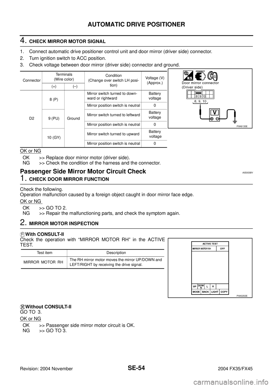
4. CHECK MIRROR MOTOR SIGNAL
1. Connect automatic drive positioner control unit and door mirror (driver side) connector.
2. Turn ignition switch to ACC position.
3. Check voltage between door mirror (driver side) connector and ground.
OK or NG
OK >> Replace door mirror motor (driver side).
NG >> Check the condition of the harness and the connector.
Passenger Side Mirror Motor Circuit CheckAIS003BV
1. CHECK DOOR MIRROR FUNCTION
Check the following.
Operation malfunction caused by a foreign object caught in door mirror face edge.
OK or NG
OK >> GO TO 2.
NG >> Repair the malfunctioning parts, and check the symptom again.
2. MIRROR MOTOR INSPECTION
With CONSULT-II
Check the operation with “MIRROR MOTOR RH” in the ACTIVE
TEST.
Without CONSULT-II
GO TO 3.
OK or NG
OK >> Passenger side mirror motor circuit is OK.
NG >> GO TO 3.
ConnectorTe r m i n a l s
(Wire color)Condition
(Change over switch LH posi-
tion)Voltage (V)
(Approx.)
(+) (–)
D28 (P)
GroundMirror switch turned to down-
ward or rightwardBattery
voltage
Mirror position switch is neutral 0
9 (PU)Mirror switch turned to leftwardBattery
voltage
Mirror position switch is neutral 0
10 (GY)Mirror switch turned to upwardBattery
voltage
Mirror position switch is neutral 0
PIIA6130E
Test item Description
MIRROR MOTOR RHThe RH mirror motor moves the mirror UP/DOWN and
LEFT/RIGHT by receiving the drive signal.
PIIA0202E
Page 4184 of 4449
AUTOMATIC DRIVE POSITIONER
SE-55
C
D
E
F
G
H
J
K
L
MA
B
SE
Revision: 2004 November 2004 FX35/FX45
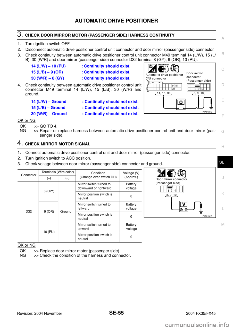
3. CHECK DOOR MIRROR MOTOR (PASSENGER SIDE) HARNESS CONTINUITY
1. Turn ignition switch OFF.
2. Disconnect automatic drive positioner control unit connector and door mirror (passenger side) connector.
3. Check continuity between automatic drive positioner control unit connector M49 terminal 14 (L/W), 15 (L/
B), 30 (W/R) and door mirror (passenger side) connector D32 terminal 8 (GY), 9 (OR), 10 (PU).
4. Check continuity between automatic drive positioner control unit
connector M49 terminal 14 (L/W), 15 (L/B), 30 (W/R) and
ground.
OK or NG
OK >> GO TO 4.
NG >> Repair or replace harness between automatic drive positioner control unit and door mirror (pas-
senger side).
4. CHECK MIRROR MOTOR SIGNAL
1. Connect automatic drive positioner control unit and door mirror (passenger side) connector.
2. Turn ignition switch to ACC position.
3. Check voltage between door mirror (passenger side) connector and ground.
OK or NG
OK >> Replace door mirror motor (passenger side).
NG >> Check the condition of the harness and connector.14 (L/W) – 10 (PU) : Continuity should exist.
15 (L/B) – 9 (OR) : Continuity should exist.
30 (W/R) – 8 (GY) : Continuity should exist.
14 (L/W) – Ground : Continuity should not exist.
15 (L/B) – Ground : Continuity should not exist.
30 (W/R) – Ground : Continuity should not exist.
PIIA6133E
ConnectorTerminals (Wire color)
Condition
(Change over switch RH)Voltage (V)
(Approx.)
(+) (–)
D328 (G/Y)
GroundMirror switch turned to
downward or rightwardBattery
voltage
Mirror position switch is
neutral0
9 (OR)Mirror switch turned to
leftwardBattery
voltage
Mirror position switch is
neutral0
10 (PU)Mirror switch turned to
upwardBattery
voltage
Mirror position switch is
neutral0
PIIA6132E
Page 4185 of 4449
SE-56
AUTOMATIC DRIVE POSITIONER
Revision: 2004 November 2004 FX35/FX45
Sliding Sensor Circuit CheckAIS002XS
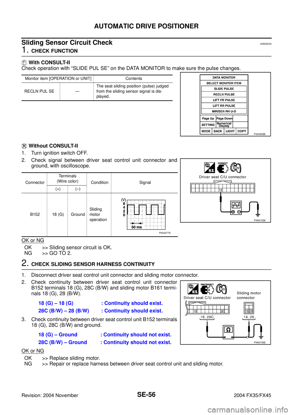
1. CHECK FUNCTION
With CONSULT-II
Check operation with “SLIDE PUL SE” on the DATA MONITOR to make sure the pulse changes.
Without CONSULT-II
1. Turn ignition switch OFF.
2. Check signal between driver seat control unit connector and
ground, with oscilloscope.
OK or NG
OK >> Sliding sensor circuit is OK.
NG >> GO TO 2.
2. CHECK SLIDING SENSOR HARNESS CONTINUITY
1. Disconnect driver seat control unit connector and sliding motor connector.
2. Check continuity between driver seat control unit connector
B152 terminals 18 (G), 28C (B/W) and sliding motor B161 termi-
nals 18 (G), 28 (B/W).
3. Check continuity between driver seat control unit B152 terminals
18 (G), 28C (B/W) and ground.
OK or NG
OK >> Replace sliding motor.
NG >> Repair or replace harness between driver seat control unit and sliding motor.
Monitor item [OPERATION or UNIT] Contents
RECLN PUL SE —The seat sliding position (pulse) judged
from the sliding sensor signal is dis-
played.
PIIA4558E
ConnectorTerminals
(Wire color)
Condition Signal
(+) (–)
B152 18 (G) GroundSliding
motor
operation
PIIA6105E
PIIA3277E
18 (G) – 18 (G) : Continuity should exist.
28C (B/W) – 28 (B/W) : Continuity should exist.
18 (G) – Ground : Continuity should not exist.
28C (B/W) – Ground : Continuity should not exist.
PIIA6106E
Page 4186 of 4449
AUTOMATIC DRIVE POSITIONER
SE-57
C
D
E
F
G
H
J
K
L
MA
B
SE
Revision: 2004 November 2004 FX35/FX45
Reclining Sensor Circuit CheckAIS002XT
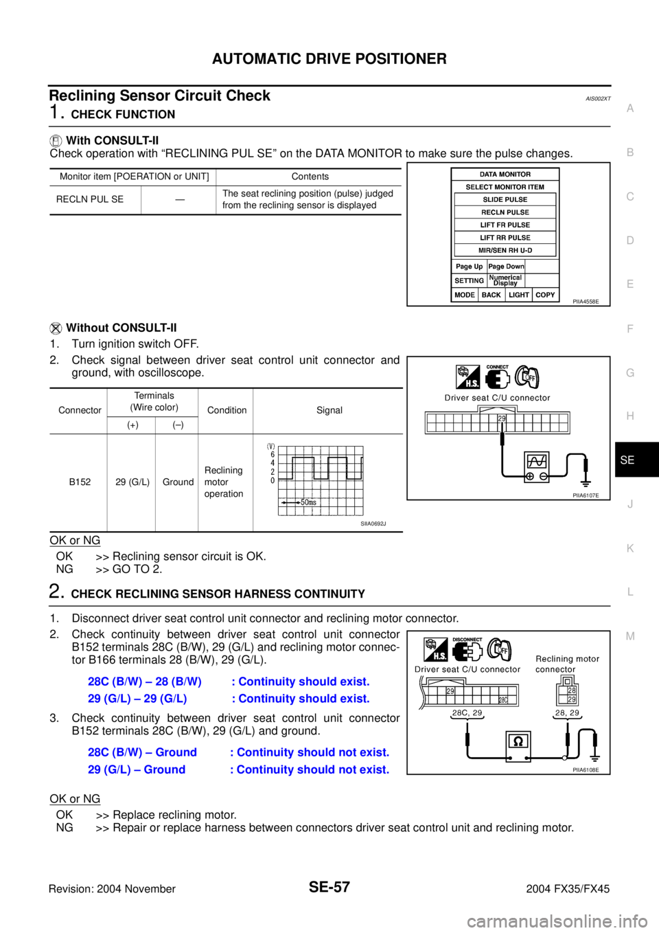
1. CHECK FUNCTION
With CONSULT-II
Check operation with “RECLINING PUL SE” on the DATA MONITOR to make sure the pulse changes.
Without CONSULT-II
1. Turn ignition switch OFF.
2. Check signal between driver seat control unit connector and
ground, with oscilloscope.
OK or NG
OK >> Reclining sensor circuit is OK.
NG >> GO TO 2.
2. CHECK RECLINING SENSOR HARNESS CONTINUITY
1. Disconnect driver seat control unit connector and reclining motor connector.
2. Check continuity between driver seat control unit connector
B152 terminals 28C (B/W), 29 (G/L) and reclining motor connec-
tor B166 terminals 28 (B/W), 29 (G/L).
3. Check continuity between driver seat control unit connector
B152 terminals 28C (B/W), 29 (G/L) and ground.
OK or NG
OK >> Replace reclining motor.
NG >> Repair or replace harness between connectors driver seat control unit and reclining motor.
Monitor item [POERATION or UNIT] Contents
RECLN PUL SE —The seat reclining position (pulse) judged
from the reclining sensor is displayed
PIIA4558E
ConnectorTerminals
(Wire color)
Condition Signal
(+) (–)
B152 29 (G/L) GroundReclining
motor
operation
PIIA6107E
SIIA0692J
28C (B/W) – 28 (B/W) : Continuity should exist.
29 (G/L) – 29 (G/L) : Continuity should exist.
28C (B/W) – Ground : Continuity should not exist.
29 (G/L) – Ground : Continuity should not exist.
PIIA6108E
Page 4187 of 4449
SE-58
AUTOMATIC DRIVE POSITIONER
Revision: 2004 November 2004 FX35/FX45
Front Lifting Sensor Circuit CheckAIS002XU
1. CHECK FUNCTION
With CONSULT-II
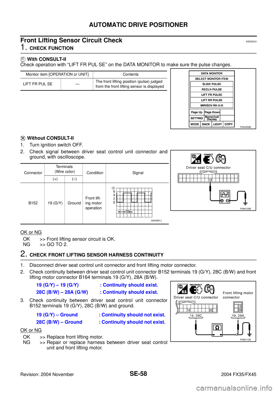
Check operation with “LIFT FR PUL SE” on the DATA MONITOR to make sure the pulse changes.
Without CONSULT-II
1. Turn ignition switch OFF.
2. Check signal between driver seat control unit connector and
ground, with oscilloscope.
OK or NG
OK >> Front lifting sensor circuit is OK.
NG >> GO TO 2.
2. CHECK FRONT LIFTING SENSOR HARNESS CONTINUITY
1. Disconnect driver seat control unit connector and front lifting motor connector.
2. Check continuity between driver seat control unit connector B152 terminals 19 (G/Y), 28C (B/W) and front
lifting motor connector B164 terminals 19 (G/Y), 28A (B/W).
3. Check continuity between driver seat control unit connector
B152 terminals 19 (G/Y), 28C (B/W) and ground.
OK or NG
OK >> Replace front lifting motor.
NG >> Repair or replace harness between driver seat control
unit and front lifting motor.
Monitor item [OPERATION or UNIT] Contents
LIFT FR PUL SE —The front lifting position (pulse) judged
from the front lifting sensor is displayed
PIIA4558E
ConnectorTe r m i n a l s
(Wire color)
Condition Signal
(+) (–)
B152 19 (G/Y) GroundFront lift-
ing motor
operation
PIIA6109E
SIIA0691J
19 (G/Y) – 19 (G/Y) : Continuity should exist.
28C (B/W) – 28A (G/W) : Continuity should exist.
19 (G/Y) – Ground : Continuity should not exist.
28C (B/W) – Ground : Continuity should not exist.
PIIA6110E
Page 4188 of 4449
AUTOMATIC DRIVE POSITIONER
SE-59
C
D
E
F
G
H
J
K
L
MA
B
SE
Revision: 2004 November 2004 FX35/FX45
Rear Lifting Sensor Circuit CheckAIS002XV
1. CHECK REAR END LIFTING SENSOR INPUT/OUTPUT SIGNAL
With CONSULT-II
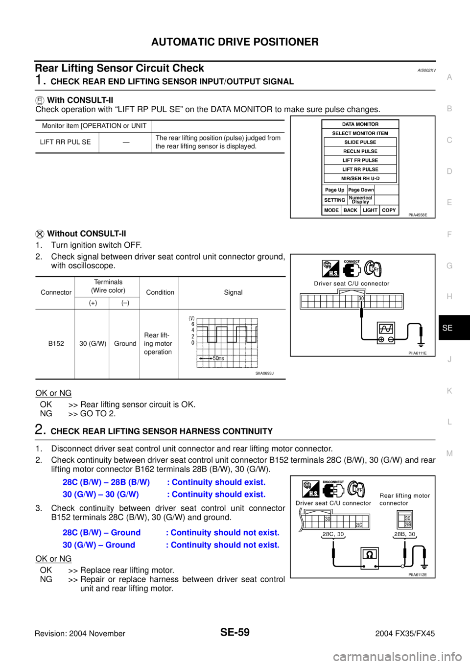
Check operation with “LIFT RP PUL SE” on the DATA MONITOR to make sure pulse changes.
Without CONSULT-II
1. Turn ignition switch OFF.
2. Check signal between driver seat control unit connector ground,
with oscilloscope.
OK or NG
OK >> Rear lifting sensor circuit is OK.
NG >> GO TO 2.
2. CHECK REAR LIFTING SENSOR HARNESS CONTINUITY
1. Disconnect driver seat control unit connector and rear lifting motor connector.
2. Check continuity between driver seat control unit connector B152 terminals 28C (B/W), 30 (G/W) and rear
lifting motor connector B162 terminals 28B (B/W), 30 (G/W).
3. Check continuity between driver seat control unit connector
B152 terminals 28C (B/W), 30 (G/W) and ground.
OK or NG
OK >> Replace rear lifting motor.
NG >> Repair or replace harness between driver seat control
unit and rear lifting motor.
Monitor item [OPERATION or UNIT
LIFT RR PUL SE —The rear lifting position (pulse) judged from
the rear lifting sensor is displayed.
PIIA4558E
ConnectorTe r m i n a l s
(Wire color)
Condition Signal
(+) (–)
B152 30 (G/W) GroundRear lift-
ing motor
operation
P I I A 6 111 E
SIIA0693J
28C (B/W) – 28B (B/W) : Continuity should exist.
30 (G/W) – 30 (G/W) : Continuity should exist.
28C (B/W) – Ground : Continuity should not exist.
30 (G/W) – Ground : Continuity should not exist.
PIIA6112E
Page 4189 of 4449
SE-60
AUTOMATIC DRIVE POSITIONER
Revision: 2004 November 2004 FX35/FX45
Telescopic Sensor Circuit CheckAIS002YB
1. CHECK FUNCTION
With CONSULT-II
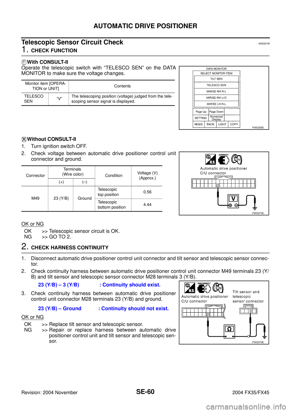
Operate the telescopic switch with “TELESCO SEN” on the DATA
MONITOR to make sure the voltage changes.
Without CONSULT-II
1. Turn ignition switch OFF.
2. Check voltage between automatic drive positioner control unit
connector and ground.
OK or NG
OK >> Telescopic sensor circuit is OK.
NG >> GO TO 2.
2. CHECK HARNESS CONTINUITY
1. Disconnect automatic drive positioner control unit connector and tilt sensor and telescopic sensor connec-
tor.
2. Check continuity harness between automatic drive positioner control unit connector M49 terminals 23 (Y/
B) and tilt sensor and telescopic sensor connector M28 terminals 3 (Y/B).
3. Check continuity harness between automatic drive positioner
control unit connector M28 terminals 23 (Y/B) and ground.
OK or NG
OK >> Replace tilt sensor and telescopic sensor.
NG >> Repair or replace harness between automatic drive
positioner control unit and tilt sensor and telescopic sen-
sor.
Monitor item [OPERA-
TION or UNIT]Contents
TELESCO
SEN“V”The telescoping position (voltage) judged from the tele-
scoping sensor signal is displayed.
PIIA0295E
ConnectorTe r m i n a l s
(Wire color)
ConditionVoltage (V)
(Approx.)
(+) (–)
M49 23 (Y/B) GroundTelescopic
top position0.56
Telescopic
bottom position4.44
PIIA5070E
23 (Y/B) – 3 (Y/B) : Continuity should exist.
23 (Y/B) – Ground : Continuity should not exist.
PIIA5079E
Page 4196 of 4449
AUTOMATIC DRIVE POSITIONER
SE-67
C
D
E
F
G
H
J
K
L
MA
B
SE
Revision: 2004 November 2004 FX35/FX45
Sliding Switch Circuit CheckAIS002Y1
1. CHECK FUNCTION
With CONSULT-II
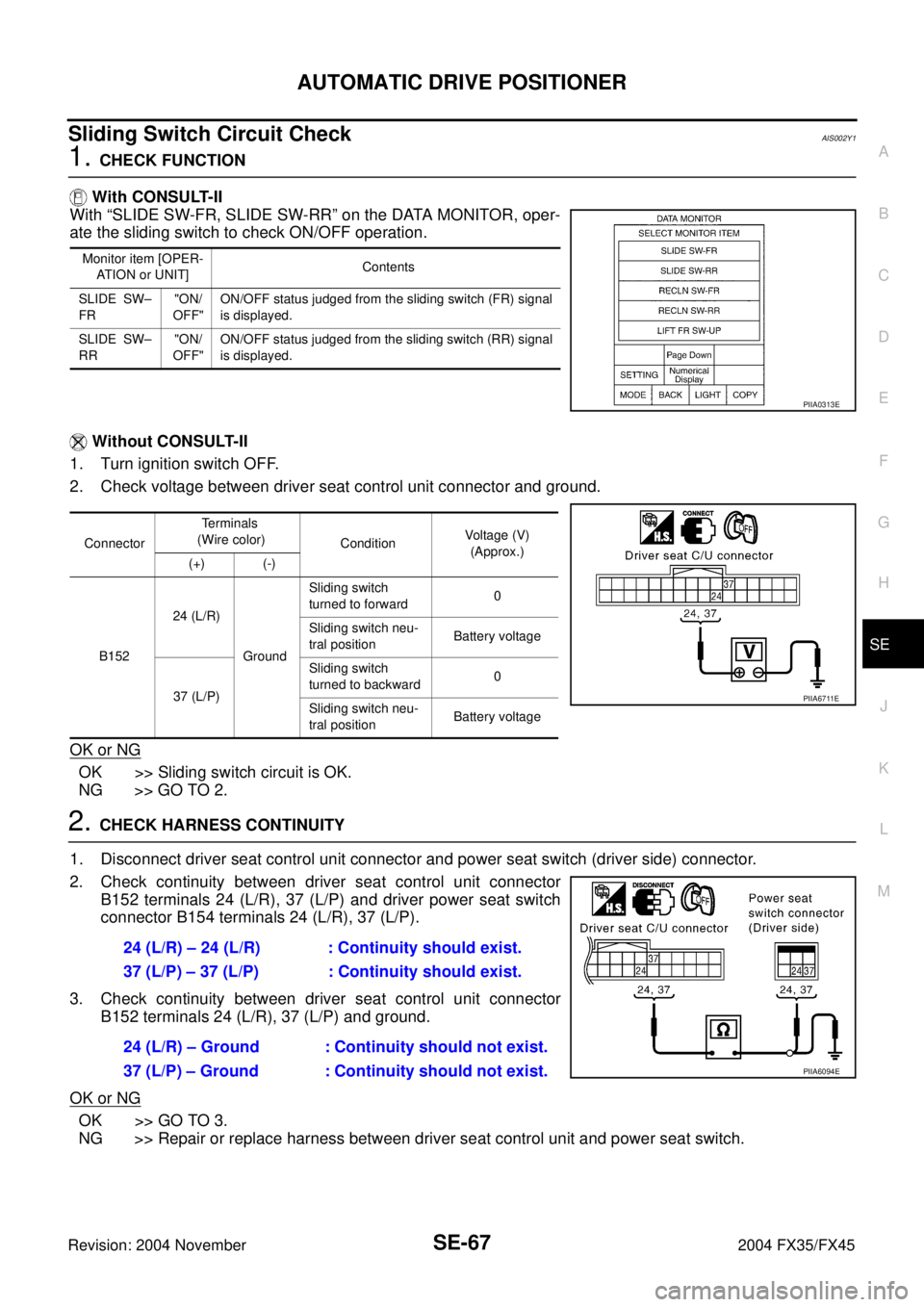
With “SLIDE SW-FR, SLIDE SW-RR” on the DATA MONITOR, oper-
ate the sliding switch to check ON/OFF operation.
Without CONSULT-II
1. Turn ignition switch OFF.
2. Check voltage between driver seat control unit connector and ground.
OK or NG
OK >> Sliding switch circuit is OK.
NG >> GO TO 2.
2. CHECK HARNESS CONTINUITY
1. Disconnect driver seat control unit connector and power seat switch (driver side) connector.
2. Check continuity between driver seat control unit connector
B152 terminals 24 (L/R), 37 (L/P) and driver power seat switch
connector B154 terminals 24 (L/R), 37 (L/P).
3. Check continuity between driver seat control unit connector
B152 terminals 24 (L/R), 37 (L/P) and ground.
OK or NG
OK >> GO TO 3.
NG >> Repair or replace harness between driver seat control unit and power seat switch.
Monitor item [OPER-
ATION or UNIT]Contents
SLIDE SW–
FR"ON/
OFF"ON/OFF status judged from the sliding switch (FR) signal
is displayed.
SLIDE SW–
RR"ON/
OFF"ON/OFF status judged from the sliding switch (RR) signal
is displayed.
PIIA0313E
ConnectorTe r m i n a l s
(Wire color)
ConditionVoltage (V)
(Approx.)
(+) (-)
B15224 (L/R)
GroundSliding switch
turned to forward0
Sliding switch neu-
tral positionBattery voltage
37 (L/P)Sliding switch
turned to backward0
Sliding switch neu-
tral positionBattery voltage
PIIA6711E
24 (L/R) – 24 (L/R) : Continuity should exist.
37 (L/P) – 37 (L/P) : Continuity should exist.
24 (L/R) – Ground : Continuity should not exist.
37 (L/P) – Ground : Continuity should not exist.
PIIA6094E