Page 641 of 4449
AV-50
AUDIO ANTENNA
Revision: 2004 November 2004 FX35/FX45
Wiring Diagram — M/ANT —AKS007WF
TKWM0569E
Page 651 of 4449
AV-60
INTEGRATED DISPLAY SYSTEM
Revision: 2004 November 2004 FX35/FX45
CAN Communication System DescriptionAKS00BO6
CAN (Controller Area Network) is a serial communication line for real time application. It is an on-vehicle mul-
tiplex communication line with high data communication speed and excellent error detection ability. Many elec-
tronic control units are equipped onto a vehicle, and each control unit shares information and links with other
control units during operation (not independent). In CAN communication, control units are connected with 2
communication lines (CAN H line, CAN L line) allowing a high rate of information transmission with less wiring.
Each control unit transmits/receives data but selectively reads required data only.
Page 654 of 4449
INTEGRATED DISPLAY SYSTEM
AV-63
C
D
E
F
G
H
I
J
L
MA
B
AV
Revision: 2004 November 2004 FX35/FX45
Wiring Diagram — INF/D — AKS00BOA
TKWM0580E
Page 660 of 4449
INTEGRATED DISPLAY SYSTEM
AV-69
C
D
E
F
G
H
I
J
L
MA
B
AV
Revision: 2004 November 2004 FX35/FX45
Wiring Diagram — COMM —AKS00BOC
TKWM0592E
Page 696 of 4449
NAVIGATION SYSTEM
AV-105
C
D
E
F
G
H
I
J
L
MA
B
AV
Revision: 2004 November 2004 FX35/FX45
CAN Communication System DescriptionAKS007Z3
CAN (Controller Area Network) is a serial communication line for real time application. It is an on-vehicle mul-
tiplex communication line with high data communication speed and excellent error detection ability. Many elec-
tronic control units are equipped onto a vehicle, and each control unit shares information and links with other
control units during operation (not independent). In CAN communication, control units are connected with 2
communication lines (CAN H line, CAN L line) allowing a high rate of information transmission with less wiring.
Each control unit transmits/receives data but selectively reads required data only.
CAN Communication UnitAKS007Z0
Refer to LAN-6, "CAN Communication Unit" .
Component Parts Location and Harness Connector LocationAKS007IR
PKIA2910E
Page 698 of 4449
NAVIGATION SYSTEM
AV-107
C
D
E
F
G
H
I
J
L
MA
B
AV
Revision: 2004 November 2004 FX35/FX45
Wiring Diagram —NAVI—AKS007IT
TKWM1289E
Page 707 of 4449
AV-116
NAVIGATION SYSTEM
Revision: 2004 November 2004 FX35/FX45
Wiring Diagram — COMM —AKS007IU
TKWM0586E
Page 724 of 4449

NAVIGATION SYSTEM
AV-133
C
D
E
F
G
H
I
J
L
MA
B
AV
Revision: 2004 November 2004 FX35/FX45
SELF–DIAGNOSIS RESULT
Quick reference table
1. Select a malfunctioning diagnosis No. in the diagnosis result quick reference table.
2. Find estimated malfunctioning system in the diagnosis No. table and perform check by referring to AV-
11 6 , "Wiring Diagram — COMM —" .
3. Turn the ignition switch OFF and perform self-diagnosis again.
*: DCU = Display control unit
CAUTION:
�When A/C and AV switch has a malfunction, you cannot start. Refer to AV- 1 7 1 , "Unable to Oper-
ate All of A/C and AV switch (Unable to start Self-Diagnosis)" .
�When display has a malfunction, you cannot start. Refer to AV- 1 6 7 , "Screen is Not Shown" .
Self-Diagnosis Codes
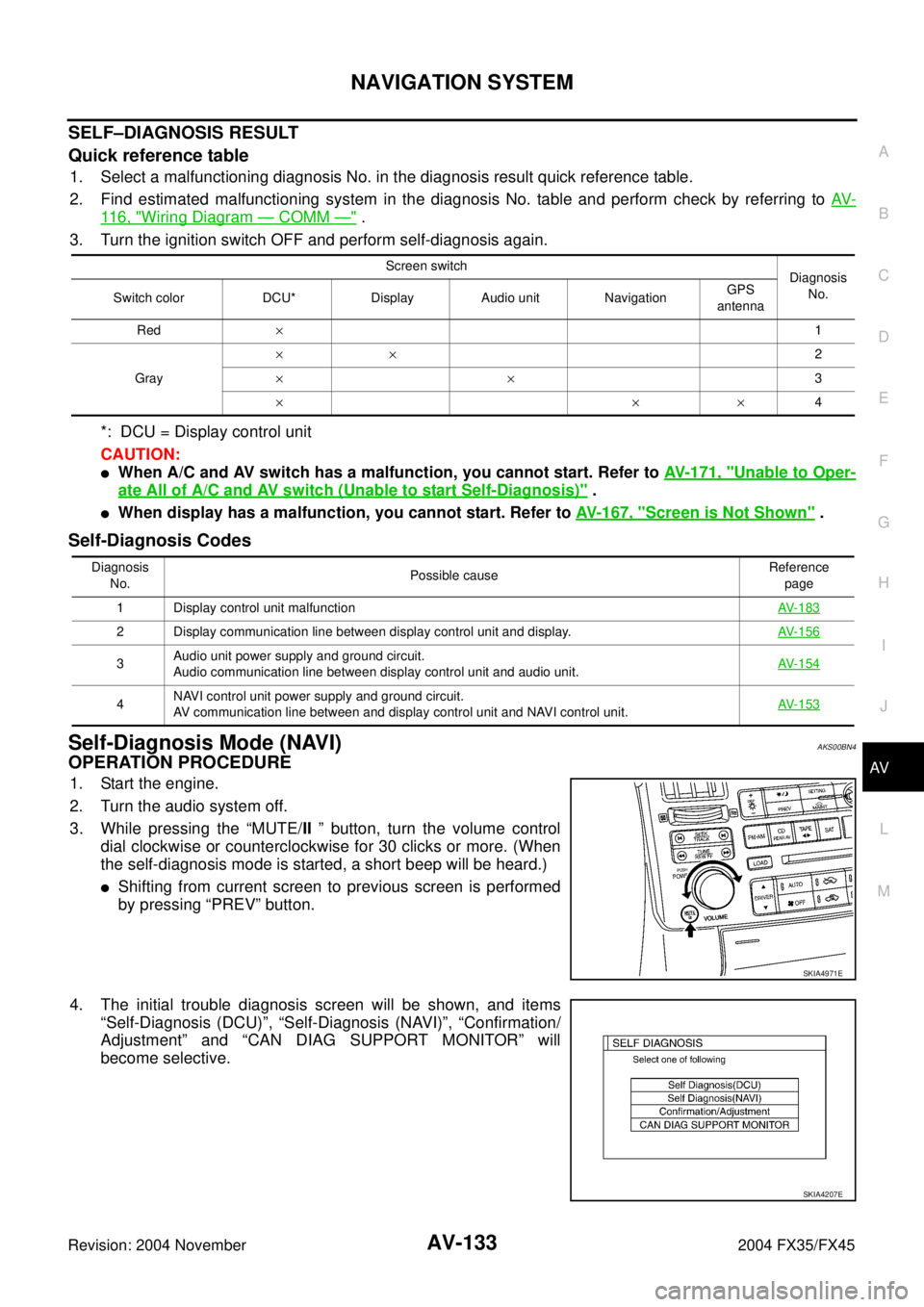
Self-Diagnosis Mode (NAVI)AKS00BN4
OPERATION PROCEDURE
1. Start the engine.
2. Turn the audio system off.
3. While pressing the “MUTE/II ” button, turn the volume control
dial clockwise or counterclockwise for 30 clicks or more. (When
the self-diagnosis mode is started, a short beep will be heard.)
�Shifting from current screen to previous screen is performed
by pressing “PREV” button.
4. The initial trouble diagnosis screen will be shown, and items
“Self-Diagnosis (DCU)”, “Self-Diagnosis (NAVI)”, “Confirmation/
Adjustment” and “CAN DIAG SUPPORT MONITOR” will
become selective.
Screen switch
Diagnosis
No.
Switch color DCU* Display Audio unit NavigationGPS
antenna
Red×1
Gray××2
××3
×××4
Diagnosis
No.Possible causeReference
page
1 Display control unit malfunctionAV-183
2 Display communication line between display control unit and display. AV-156
3Audio unit power supply and ground circuit.
Audio communication line between display control unit and audio unit.AV-154
4NAVI control unit power supply and ground circuit.
AV communication line between and display control unit and NAVI control unit.AV-153
SKIA4971E
SKIA4207E