Page 903 of 4449
BL-96
INTELLIGENT KEY SYSTEM
Revision: 2004 November 2004 FX35/FX45
Wiring Diagram — I/KEY—AIS004MZ
TIWM0426E
Page 974 of 4449
BACK DOOR AUTO CLOSURE SYSTEM
BL-167
C
D
E
F
G
H
J
K
L
MA
B
BL
Revision: 2004 November 2004 FX35/FX45
Wiring Diagram — B/CLOS —AIS004OF
TIWH0047E
Page 992 of 4449
VEHICLE SECURITY (THEFT WARNING) SYSTEM
BL-185
C
D
E
F
G
H
J
K
L
MA
B
BL
Revision: 2004 November 2004 FX35/FX45
CAN Communication System DescriptionAIS004OU
CAN (Controller Area Network) is a serial communication line for real time application. It is an on-vehicle mul-
tiplex communication line with high data communication speed and excellent error detection ability. Many elec-
tronic control units are equipped onto a vehicle, and each control unit shares information and links with other
control units during operation (not independent). In CAN communication, control units are connected with 2
communication lines (CAN H line, CAN L line) allowing a high rate of information transmission with less wiring.
Each control unit transmits/receives data but selectively reads required data only.
CAN Communication UnitAIS004OV
Refer to LAN-6, "CAN COMMUNICATION" .
Page 994 of 4449
VEHICLE SECURITY (THEFT WARNING) SYSTEM
BL-187
C
D
E
F
G
H
J
K
L
MA
B
BL
Revision: 2004 November 2004 FX35/FX45
Wiring Diagram -VEHSEC-AIS004OX
TIWM0334E
Page 1016 of 4449
IVIS (INFINITI VEHICLE IMMOBILIZER SYSTEM-NATS)
BL-209
C
D
E
F
G
H
J
K
L
MA
B
BL
Revision: 2004 November 2004 FX35/FX45
Wiring Diagram – NATS –AIS004PE
MODELS WITH INTELLIGENT KEY SYSTEM
TIWM0422E
Page 1035 of 4449
BL-228
INTEGRATED HOMELINK TRANSMITTER
Revision: 2004 November 2004 FX35/FX45
INTEGRATED HOMELINK TRANSMITTERPFP:96401
Wiring Diagram —TRNSCV—AIS004PU
TIWM0340E
Page 1096 of 4449

PRECAUTIONS
BR-3
C
D
E
G
H
I
J
K
L
MA
B
BR
Revision: 2004 November 2004 FX35/FX45
PRECAUTIONSPFP:00001
Precautions for Supplemental Restraint System (SRS) “AIR BAG” and “SEAT
BELT PRE-TENSIONER”
AFS0028A
The Supplemental Restraint System such as “AIR BAG” and “SEAT BELT PRE-TENSIONER”, used along
with a front seat belt, helps to reduce the risk or severity of injury to the driver and front passenger for certain
types of collision. This system includes seat belt switch inputs and dual stage front air bag modules. The SRS
system uses the seat belt switches to determine the front air bag deployment, and may only deploy one front
air bag, depending on the severity of a collision and whether the front occupants are belted or unbelted.
Information necessary to service the system safely is included in the SRS and SB section of this Service Man-
ual.
WARNING:
�To avoid rendering the SRS inoperative, which could increase the risk of personal injury or death
in the event of a collision which would result in air bag inflation, all maintenance must be per-
formed by an authorized NISSAN/INFINITI dealer.
�Improper maintenance, including incorrect removal and installation of the SRS, can lead to per-
sonal injury caused by unintentional activation of the system. For removal of Spiral Cable and Air
Bag Module, see the SRS section.
�Do not use electrical test equipment on any circuit related to the SRS unless instructed to in this
Service Manual. SRS wiring harnesses can be identified by yellow and/or orange harnesses or
harness connectors.
Precautions for Brake SystemAFS001MQ
�Recommended fluid is brake fluid “DOT 3”.
�Do not reuse drained brake fluid.
�Be careful not to splash brake fluid on painted areas.
�To clean or wash all parts of master cylinder, disc brake caliper and wheel cylinder, use clean brake fluid.
�Do not use mineral oils such as gasoline or kerosene. They will ruin rubber parts of the hydraulic system.
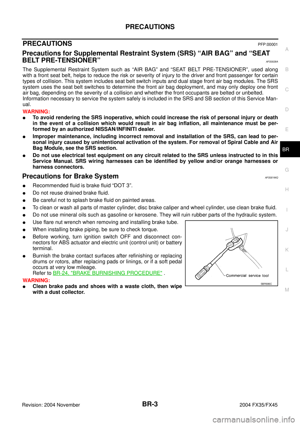
�Use flare nut wrench when removing and installing brake tube.
�When installing brake piping, be sure to check torque.
�Before working, turn ignition switch OFF and disconnect con-
nectors for ABS actuator and electric unit (control unit) or battery
terminal.
�Burnish the brake contact surfaces after refinishing or replacing
drums or rotors, after replacing pads or linings, or if a soft pedal
occurs at very low mileage.
Refer to BR-24, "
BRAKE BURNISHING PROCEDURE" .
WARNING:
�Clean brake pads and shoes with a waste cloth, then wipe
with a dust collector.SBR686C
Page 1126 of 4449

BRC-1
BRAKE CONTROL SYSTEM
F BRAKES
CONTENTS
C
D
E
G
H
I
J
K
L
M
SECTION BRC
A
B
BRC
Revision: 2004 November 2004 FX35/FX45
BRAKE CONTROL SYSTEM
VDC/TCS/ABS
PRECAUTIONS .......................................................... 3
Precautions for Supplemental Restraint System
(SRS) “AIR BAG” and “SEAT BELT PRE-TEN-
SIONER” .................................................................. 3
Precautions for Brake System .................................. 3
Precautions for Brake Control .................................. 3
PREPARATION ........................................................... 5
Special Service Tools ............................................... 5
Commercial Service Tools ........................................ 5
ON-VEHICLE SERVICE ............................................. 6
Adjustment of Steering Angle Sensor Neutral Posi-
tion ........................................................................... 6
Calibration of Decel G-sensor (AWD Model) ............ 6
SYSTEM DESCRIPTION ............................................ 8
System Diagram ....................................................... 8
VDC Function ........................................................... 8
TCS Function ........................................................... 8
ABS Function ........................................................... 8
EBD Function ........................................................... 9
Fail-Safe Function .................................................... 9
VDC / TCS SYSTEM ............................................. 9
ABS, EBD SYSTEM .............................................. 9
Hydraulic Circuit Diagram ...................................... 10
CAN COMMUNICATION ...........................................11
System Description ................................................. 11
TROUBLE DIAGNOSIS ............................................ 12
How to Proceed With Diagnosis ............................. 12
BASIC CONCEPT ............................................... 12
DIAGNOSIS FLOWCHART ................................ 13
ASKING COMPLAINTS ...................................... 14
EXAMPLE OF DIAGNOSIS SHEET ................... 14
Component Installation Location ............................ 15
Schematic .............................................................. 16
Wiring Diagram — VDC — ..................................... 17
Control Unit Input/Output Signal Standard ............. 23
REFERENCE VALUE FROM CONSULT-II ......... 23
CONSULT-II Functions ........................................... 25
CONSULT-II MAIN FUNCTION ........................... 25
CONSULT-II BASIC OPERATION PROCEDURE ... 26
SELF-DIAGNOSIS .............................................. 27
DATA MONITOR ................................................. 30
ACTIVE TEST ..................................................... 33
For Fast and Accurate Diagnosis ........................... 35
PRECAUTIONS FOR DIAGNOSIS ..................... 35
Basic Inspection ..................................................... 36
BASIC INSPECTION 1: BRAKE FLUID
AMOUNT, LEAKS, AND BRAKE PADS INSPEC-
TION .................................................................... 36
BASIC INSPECTION 2: POWER SYSTEM TER-
MINAL LOOSENESS AND BATTERY INSPEC-
TION .................................................................... 36
BASIC INSPECTION 3: ABS WARNING LAMP,
VDC OFF INDICATOR LAMP, SLIP INDICATOR
LAMP AND BRAKE WARNING LAMP INSPEC-
TION .................................................................... 37
Inspection 1: Wheel Sensor System ....................... 37
Inspection 2: Engine System .................................. 39
Inspection 3: VDC/TCS/ABS Control Unit System ... 40
Inspection 4: Pressure Sensor System .................. 40
Inspection 5: Steering Angle Sensor System ......... 42
Inspection 6: Yaw Rate/Side G-Sensor (2WD
model), Yaw Rate/Side/Decel G-sensor (AWD mod-
els) System ............................................................. 44
Inspection 7: Solenoid and VDC Change-Over
Valve System .......................................................... 46
Inspection 8: Actuator Motor System ...................... 47
Inspection 9: ABS Actuator and Electric Unit (Con-
trol Unit) Power Supply and Ground System .......... 48
Inspection 10: Stop Lamp Switch System .............. 50
Inspection 11: Brake Fluid Level Switch System .... 51
Inspection 12: When “ST ANG SEN SIGNAL”
Appears on Self-Diagnosis Results Display ........... 52
Inspection 13: When “DECEL G SEN SET” Appears
on Self-Diagnosis Results Display (AWD Model) ... 52
Inspection 14: CAN Communication System .......... 53
Component Inspection ............................................ 53
VDC OFF SWITCH ............................................. 53
Symptom 1: Excessive ABS Function Operation