Page 190 of 4449
DTC P0705 PARK/NEUTRAL POSITION SWITCH
AT-113
D
E
F
G
H
I
J
K
L
MA
B
AT
Revision: 2004 November 2004 FX35/FX45
Wiring Diagram — AT — PNP/SWACS007B2
TCWM0248E
Page 191 of 4449

AT-114
DTC P0705 PARK/NEUTRAL POSITION SWITCH
Revision: 2004 November 2004 FX35/FX45
Diagnostic ProcedureACS007B3
1. CHECK PNP SW CIRCUIT
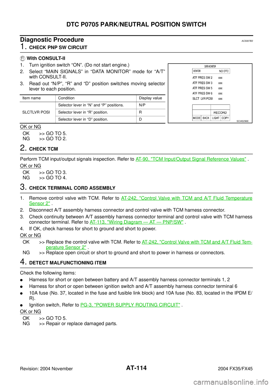
With CONSULT-II
1. Turn ignition switch “ON”. (Do not start engine.)
2. Select “MAIN SIGNALS” in “DATA MONITOR” mode for “A/T”
with CONSULT-II.
3. Read out “N/P”, “R” and “D” position switches moving selector
lever to each position.
OK or NG
OK >> GO TO 5.
NG >> GO TO 2.
2. CHECK TCM
Perform TCM input/output signals inspection. Refer to AT- 9 0 , "
TCM Input/Output Signal Reference Values" .
OK or NG
OK >> GO TO 3.
NG >> GO TO 4.
3. CHECK TERMINAL CORD ASSEMBLY
1. Remove control valve with TCM. Refer to AT- 2 4 2 , "
Control Valve with TCM and A/T Fluid Temperature
Sensor 2" .
2. Disconnect A/T assembly harness connector and control valve with TCM harness connector.
3. Check continuity between A/T assembly harness connector terminal and control valve with TCM harness
connector terminal. Refer to AT- 11 3 , "
Wiring Diagram — AT — PNP/SW" .
4. If OK, check harness for short to ground and short to power.
OK or NG
OK >> Replace the control valve with TCM. Refer to AT- 2 4 2 , "Control Valve with TCM and A/T Fluid Tem-
perature Sensor 2" .
NG >> Replace open circuit or short to ground and short to power in harness or connectors.
4. DETECT MALFUNCTIONING ITEM
Check the following items:
�Harness for short or open between battery and A/T assembly harness connector terminals 1, 2
�Harness for short or open between ignition switch and A/T assembly harness connector terminal 6
�10A fuse (No. 37, located in the fuse and fusible link block) and 10A fuse (No. 83, located in the IPDM E/
R).
�Ignition switch, Refer to PG-3, "POWER SUPPLY ROUTING CIRCUIT" .
OK or NG
OK >> GO TO 5.
NG >> Repair or replace damaged parts.
Item name Condition Display value
SLCTLVR POSISelector lever in “N” and “P” positions. N/P
Selector lever in “R” position. R
Selector lever in “D” position. D
SCIA5296E
Page 195 of 4449
AT-118
DTC P0720 VEHICLE SPEED SENSOR A/T (REVOLUTION SENSOR)
Revision: 2004 November 2004 FX35/FX45
Wiring Diagram — AT — VSSA/TACS007B9
TCWM0249E
Page 196 of 4449

DTC P0720 VEHICLE SPEED SENSOR A/T (REVOLUTION SENSOR)
AT-119
D
E
F
G
H
I
J
K
L
MA
B
AT
Revision: 2004 November 2004 FX35/FX45
Diagnostic ProcedureACS007BA
1. CHECK INPUT SIGNALS
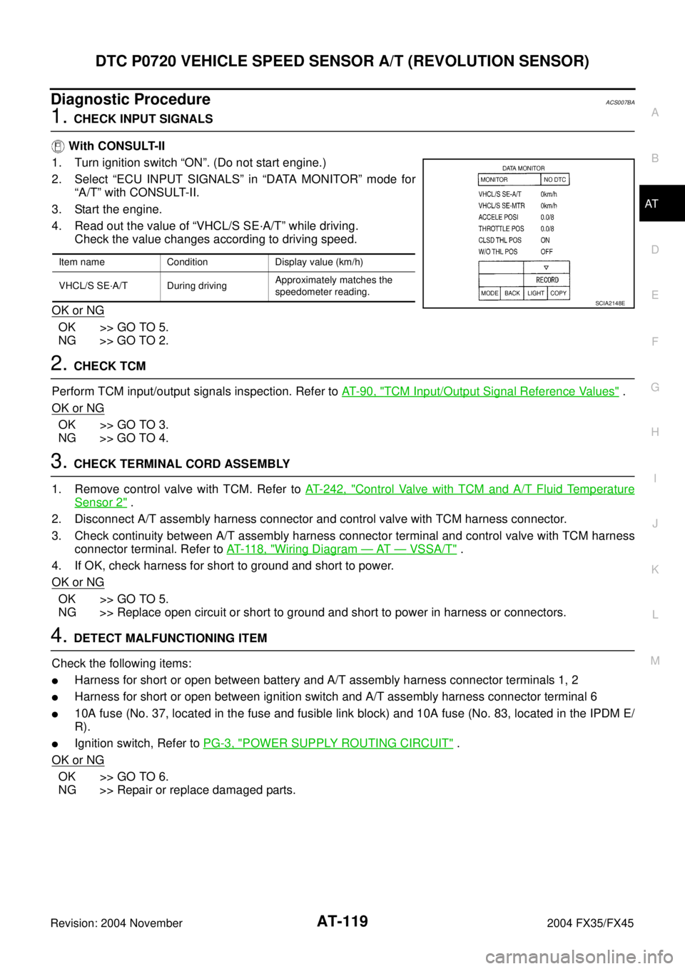
With CONSULT-II
1. Turn ignition switch “ON”. (Do not start engine.)
2. Select “ECU INPUT SIGNALS” in “DATA MONITOR” mode for
“A/T” with CONSULT-II.
3. Start the engine.
4. Read out the value of “VHCL/S SE·A/T” while driving.
Check the value changes according to driving speed.
OK or NG
OK >> GO TO 5.
NG >> GO TO 2.
2. CHECK TCM
Perform TCM input/output signals inspection. Refer to AT- 9 0 , "
TCM Input/Output Signal Reference Values" .
OK or NG
OK >> GO TO 3.
NG >> GO TO 4.
3. CHECK TERMINAL CORD ASSEMBLY
1. Remove control valve with TCM. Refer to AT- 2 4 2 , "
Control Valve with TCM and A/T Fluid Temperature
Sensor 2" .
2. Disconnect A/T assembly harness connector and control valve with TCM harness connector.
3. Check continuity between A/T assembly harness connector terminal and control valve with TCM harness
connector terminal. Refer to AT- 11 8 , "
Wiring Diagram — AT — VSSA/T" .
4. If OK, check harness for short to ground and short to power.
OK or NG
OK >> GO TO 5.
NG >> Replace open circuit or short to ground and short to power in harness or connectors.
4. DETECT MALFUNCTIONING ITEM
Check the following items:
�Harness for short or open between battery and A/T assembly harness connector terminals 1, 2
�Harness for short or open between ignition switch and A/T assembly harness connector terminal 6
�10A fuse (No. 37, located in the fuse and fusible link block) and 10A fuse (No. 83, located in the IPDM E/
R).
�Ignition switch, Refer to PG-3, "POWER SUPPLY ROUTING CIRCUIT" .
OK or NG
OK >> GO TO 6.
NG >> Repair or replace damaged parts.
Item name Condition Display value (km/h)
VHCL/S SE·A/T During drivingApproximately matches the
speedometer reading.
SCIA2148E
Page 207 of 4449
AT-130
DTC P1701 TRANSMISSION CONTROL MODULE (POWER SUPPLY)
Revision: 2004 November 2004 FX35/FX45
Wiring Diagram — AT — POWERACS007C4
TCWM0250E
Page 208 of 4449

DTC P1701 TRANSMISSION CONTROL MODULE (POWER SUPPLY)
AT-131
D
E
F
G
H
I
J
K
L
MA
B
AT
Revision: 2004 November 2004 FX35/FX45
TCM terminals and data are reference value. Measured between each terminal and ground.
Diagnostic ProcedureACS007C5
1. CHECK TCM POWER SOURCE STEP 1
1. Turn ignition switch “OFF”.
2. Disconnect A/T assembly harness connector.
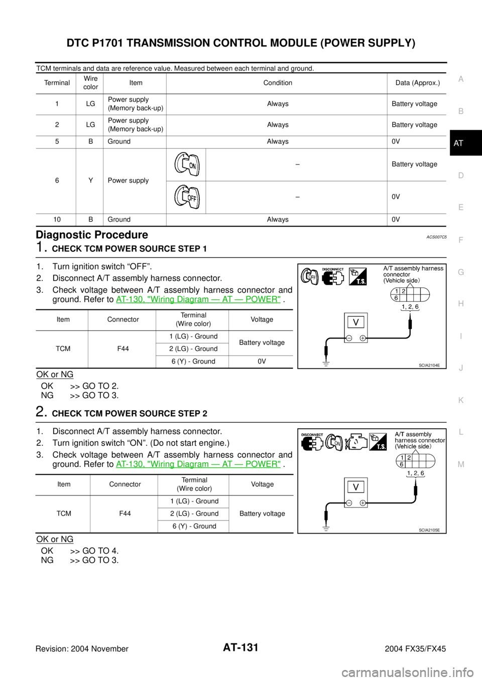
3. Check voltage between A/T assembly harness connector and
ground. Refer to AT- 1 3 0 , "
Wiring Diagram — AT — POWER" .
OK or NG
OK >> GO TO 2.
NG >> GO TO 3.
2. CHECK TCM POWER SOURCE STEP 2
1. Disconnect A/T assembly harness connector.
2. Turn ignition switch “ON”. (Do not start engine.)
3. Check voltage between A/T assembly harness connector and
ground. Refer to AT- 1 3 0 , "
Wiring Diagram — AT — POWER" .
OK or NG
OK >> GO TO 4.
NG >> GO TO 3.
TerminalWire
colorItem Condition Data (Approx.)
1LGPower supply
(Memory back-up)Always Battery voltage
2LGPower supply
(Memory back-up)Always Battery voltage
5 B Ground Always 0V
6 Y Power supply– Battery voltage
–0V
10 B Ground Always 0V
Item ConnectorTerminal
(Wire color)Voltage
TCM F441 (LG) - Ground
Battery voltage
2 (LG) - Ground
6 (Y) - Ground 0V
SCIA2104E
Item ConnectorTerminal
(Wire color)Voltag e
TCM F441 (LG) - Ground
Battery voltage 2 (LG) - Ground
6 (Y) - Ground
SCIA2105E
Page 209 of 4449

AT-132
DTC P1701 TRANSMISSION CONTROL MODULE (POWER SUPPLY)
Revision: 2004 November 2004 FX35/FX45
3. DETECT MALFUNCTIONING ITEM
Check the following items:
�Harness for short or open between battery and A/T assembly harness connector terminals 1, 2
�Harness for short or open between ignition switch and A/T assembly harness connector terminal 6
�10A fuse (No. 37, located in the fuse and fusible link block) and 10A fuse (No. 83, located in the IPDM E/
R)
�Ignition switch, Refer to PG-3, "POWER SUPPLY ROUTING CIRCUIT" .
OK or NG
OK >> GO TO 4.
NG >> Repair or replace damaged parts.
4. CHECK TCM GROUND CIRCUIT
1. Turn ignition switch “OFF”.
2. Disconnect A/T assembly harness connector.
3. Check continuity between A/T assembly harness connector ter-
minal 5 (B), 10 (B) and ground. Refer to AT- 1 3 0 , "
Wiring Dia-
gram — AT — POWER" .
If OK, check harness for short to ground and short to power.
OK or NG
OK >> GO TO 5.
NG >> Repair open circuit or short to ground or short to power
in harness or connectors.
5. CHECK DTC
Perform “DTC Confirmation Procedure”.
�Refer to AT- 1 2 9 , "DTC Confirmation Procedure" .
OK or NG
OK >>INSPECTION END
NG >> GO TO 6.
6. CHECK TERMINAL CORD ASSEMBLY
1. Remove control valve with TCM. Refer to AT- 2 4 2 , "
Control Valve with TCM and A/T Fluid Temperature
Sensor 2" .
2. Disconnect A/T assembly harness connector and control valve with TCM harness connector.
3. Check continuity between A/T assembly harness connector terminal and control valve with TCM harness
connector terminal. Refer to AT- 1 3 0 , "
Wiring Diagram — AT — POWER" .
4. If OK, check harness for short to ground and short to power.
OK or NG
OK >> Replace the control valve with TCM. Refer to AT- 2 4 2 , "Control Valve with TCM and A/T Fluid Tem-
perature Sensor 2" .
NG >> Replace open circuit or short to ground and short to power in harness or connectors.Continuity should exist.
SCIA2106E
Page 217 of 4449
AT-140
DTC P1710 A/T FLUID TEMPERATURE SENSOR CIRCUIT
Revision: 2004 November 2004 FX35/FX45
Wiring Diagram — AT — FTSACS007CW
TCWM0251E