Page 219 of 4449

AT-142
DTC P1710 A/T FLUID TEMPERATURE SENSOR CIRCUIT
Revision: 2004 November 2004 FX35/FX45
5. CHECK TERMINAL CORD ASSEMBLY
1. Remove control valve with TCM. Refer to AT- 2 4 2 , "
Control Valve with TCM and A/T Fluid Temperature
Sensor 2" .
2. Disconnect A/T assembly harness connector and control valve with TCM harness connector.
3. Check continuity between A/T assembly harness connector terminal and control valve with TCM harness
connector terminal. Refer to AT- 1 4 0 , "
Wiring Diagram — AT — FTS" .
4. If OK, check harness for short to ground and short to power.
OK or NG
OK >> Replace the control valve with TCM. Refer to AT- 2 4 2 , "Control Valve with TCM and A/T Fluid Tem-
perature Sensor 2" .
NG >> Replace open circuit or short to ground and short to power in harness or connectors.
6. DETECT MALFUNCTIONING ITEM
Check the following items:
�Harness for short or open between battery and A/T assembly harness connector terminals 1, 2
�Harness for short or open between ignition switch and A/T assembly harness connector terminal 6
�10A fuse (No. 37, located in the fuse and fusible link block) and 10A fuse (No. 83, located in the IPDM E/
R).
�Ignition switch, Refer to PG-3, "POWER SUPPLY ROUTING CIRCUIT" .
OK or NG
OK >> GO TO 7.
NG >> Repair or replace damaged parts.
7. CHECK DTC
Perform “DTC Confirmation Procedure”.
�Refer to AT- 1 3 9 , "DTC Confirmation Procedure" .
OK or NG
OK >>INSPECTION END
NG >> GO TO 3.
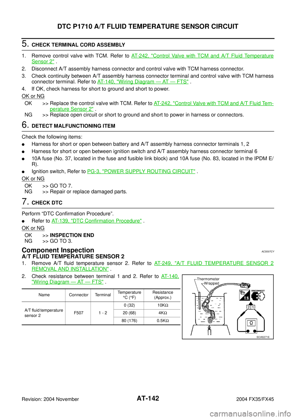
Component InspectionACS007CY
A/T FLUID TEMPERATURE SENSOR 2
1. Remove A/T fluid temperature sensor 2. Refer to AT- 2 4 9 , "A/T FLUID TEMPERATURE SENSOR 2
REMOVAL AND INSTALLATION" .
2. Check resistance between terminal 1 and 2. Refer to AT- 1 4 0 ,
"Wiring Diagram — AT — FTS" .
Name Connector TerminalTemperature
°C (°F)Resistance
(Approx.)
A/T fluid temperature
sensor 2F507 1 - 20 (32) 10KΩ
20 (68) 4KΩ
80 (176) 0.5KΩ
SCIA5271E
Page 250 of 4449
DTC P1815 MANUAL MODE SWITCH
AT-173
D
E
F
G
H
I
J
K
L
MA
B
AT
Revision: 2004 November 2004 FX35/FX45
Wiring Diagram — AT — MMSWACS007FG
TCWM0252E
Page 253 of 4449

AT-176
DTC P1815 MANUAL MODE SWITCH
Revision: 2004 November 2004 FX35/FX45
3. DETECT MALFUNCTIONING ITEM
Check the following items.
�Manual mode switch. Refer to AT- 1 7 6 , "Component Inspection" .
�Terminals for damage or loose connection with harness connector.
�Open circuit or short to ground or short to power in harness or connector for A/T device (manual mode
switch).
�Unified meter and A/C amp. Refer to DI-28, "UNIFIED METER AND A/C AMP" .
OK or NG
OK >> GO TO 4.
NG >> Repair or replace damaged parts.
4. CHECK DTC
Perform “DTC Confirmation Procedure”.
�Refer to AT- 1 7 2 , "DTC Confirmation Procedure" .
OK or NG
OK >>INSPECTION END
NG >> GO TO 5.
5. CHECK SELF-DIAGNOSTIC RESULTS
Perform self-diagnosis. Refer to AT- 9 4 , "
SELF-DIAGNOSTIC RESULT MODE" .
Do the self-diagnostic results indicate
“TCM-POWER SUPPLY”?
YES >> Check the TCM power circuit. Refer to AT- 1 2 9 , "DTC P1701 TRANSMISSION CONTROL MOD-
ULE (POWER SUPPLY)" .
NO >> GO TO 6.
6. DETECT MALFUNCTIONING ITEM
Check the following items:
�The A/T assembly harness connector terminals for damage or loose connection with harness connector.
OK or NG
OK >> Replace the control valve with TCM. Refer to AT- 2 4 2 , "Control Valve with TCM and A/T Fluid Tem-
perature Sensor 2" .
NG >> Repair or replace damaged parts.
Component InspectionACS007FI
MANUAL MODE SWITCH
Check continuity between terminals. Refer to AT- 1 7 3 , "Wiring Dia-
gram — AT — MMSW" .
Item Position ConnectorTerminal
(Unit side)Continuity
Manual mode
(select) switchAuto
M679 - 10
Ye s Manual 6 - 9
UP switch UP 8 - 9
DOWN switch DOWN 7 - 9
SCIA2112E
Page 264 of 4449

BRAKE SIGNAL CIRCUIT
AT-187
D
E
F
G
H
I
J
K
L
MA
B
AT
Revision: 2004 November 2004 FX35/FX45
BRAKE SIGNAL CIRCUITPFP:25320
CONSULT-II Reference ValueACS007GA
Diagnostic ProcedureACS007GB
1. CHECK CAN COMMUNICATION LINE
Perform the self-diagnosis. Refer to AT- 9 4 , "
SELF-DIAGNOSTIC RESULT MODE" , AT- 1 0 3 , "TCM SELF-
DIAGNOSTIC PROCEDURE (NO TOOLS)" .
Is a malfunction in the CAN communication indicated in the results?
YES >> Check CAN communication line. Refer to AT- 1 0 5 , "DTC U1000 CAN COMMUNICATION LINE" .
NO >> GO TO 2.
2. CHECK STOP LAMP SWITCH CIRCUIT
With CONSULT-II
1. Turn ignition switch “ON”. (Do not start engine.)
2. Select “ECU INPUT SIGNALS” in “DATA MONITOR” mode for
“A/T” with CONSULT-II.
3. Read out ON/OFF switching action of the “BRAKE SW”.
OK or NG
OK >>INSPECTION END
NG >> GO TO 3.
3. CHECK STOP LAMP SWITCH
Check continuity between stop lamp switch harness connector E210
terminals 1 and 2. Refer to AT- 1 8 8 , "
Wiring Diagram — AT — NON-
DTC" .
Check stop lamp switch after adjusting brake pedal — refer to
BR-6, "
Inspection and Adjustment" .
OK or NG
OK >> Check the following items. If NG, repair or replace dam-
aged parts.
�Harness for short or open between battery and stop lamp switch.
�Harness for short or open between stop lamp switch and unified meter and A/C amp.
NG >> Repair or replace the stop lamp switch.
Item name Condition Display value
BRAKE SWDepressed brake pedal. ON
Released brake pedal. OFF
Item name Condition Display value
BRAKE SWDepressed brake pedal. ON
Released brake pedal. OFF
PCIA0070E
Condition Continuity
When brake pedal is depressed Yes
When brake pedal is released No
SCIA2144E
Page 265 of 4449
AT-188
TROUBLE DIAGNOSIS FOR SYMPTOMS
Revision: 2004 November 2004 FX35/FX45
TROUBLE DIAGNOSIS FOR SYMPTOMSPFP:00007
Wiring Diagram — AT — NONDTCACS007GC
TCWM0254E
Page 268 of 4449

TROUBLE DIAGNOSIS FOR SYMPTOMS
AT-191
D
E
F
G
H
I
J
K
L
MA
B
AT
Revision: 2004 November 2004 FX35/FX45
TCM terminals and data are reference value. Measured between each terminal and ground.
A/T CHECK Indicator Lamp Does Not Come OnACS007GD
SYMPTOM:
A/T CHECK indicator lamp does not come on for about 2 seconds when turning ignition switch to
“ON”.
DIAGNOSTIC PROCEDURE
1. CHECK CAN COMMUNICATION LINE
Perform self-diagnosis. Refer to AT- 9 4 , "
SELF-DIAGNOSTIC RESULT MODE" , AT- 1 0 3 , "TCM SELF-DIAG-
NOSTIC PROCEDURE (NO TOOLS)" .
Is a malfunction in the CAN communication indicated in the results?
YES >> Check CAN communication line. Refer to AT- 1 0 5 , "DTC U1000 CAN COMMUNICATION LINE" .
NO >> GO TO 2.
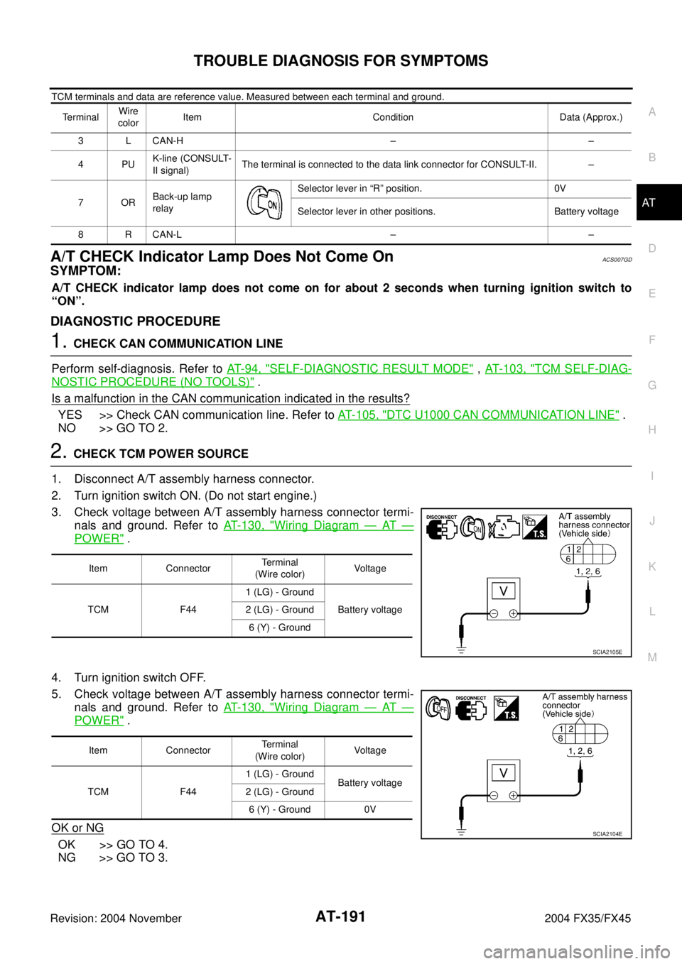
2. CHECK TCM POWER SOURCE
1. Disconnect A/T assembly harness connector.
2. Turn ignition switch ON. (Do not start engine.)
3. Check voltage between A/T assembly harness connector termi-
nals and ground. Refer to AT-130, "
Wiring Diagram — AT —
POWER" .
4. Turn ignition switch OFF.
5. Check voltage between A/T assembly harness connector termi-
nals and ground. Refer to AT-130, "
Wiring Diagram — AT —
POWER" .
OK or NG
OK >> GO TO 4.
NG >> GO TO 3.
TerminalWire
colorItem Condition Data (Approx.)
3 L CAN-H – –
4PUK-line (CONSULT-
II signal)The terminal is connected to the data link connector for CONSULT-II. –
7ORBack-up lamp
relaySelector lever in “R” position. 0V
Selector lever in other positions. Battery voltage
8 R CAN-L – –
Item ConnectorTerminal
(Wire color)Voltag e
TCM F441 (LG) - Ground
Battery voltage 2 (LG) - Ground
6 (Y) - Ground
SCIA2105E
Item ConnectorTerminal
(Wire color)Voltag e
TCM F441 (LG) - Ground
Battery voltage
2 (LG) - Ground
6 (Y) - Ground 0V
SCIA2104E
Page 269 of 4449

AT-192
TROUBLE DIAGNOSIS FOR SYMPTOMS
Revision: 2004 November 2004 FX35/FX45
3. DETECT MALFUNCTIONING ITEM
Check the following items:
�Harness for short or open between battery and A/T assembly harness connector terminals 1, 2.
�Harness for short or open between ignition switch and A/T assembly harness connector terminal 6
�10A fuse (No.37, located in the fuse and fusible link box)
�10A fuse (No.83, located in the IPDM E/R)
�Ignition switch, Refer to PG-3, "POWER SUPPLY ROUTING CIRCUIT" .
OK or NG
OK >> GO TO 4.
NG >> Repair or replace damaged parts.
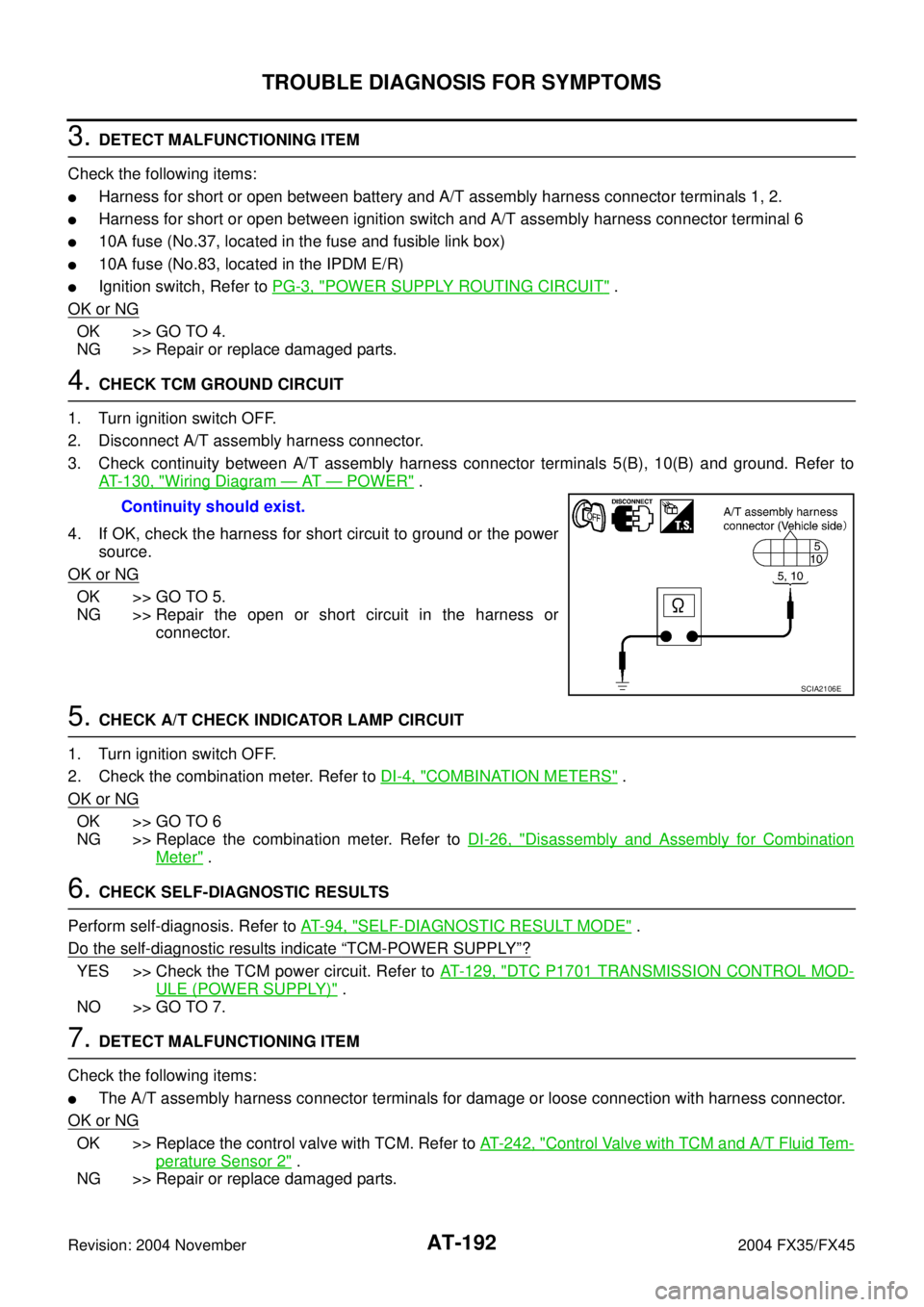
4. CHECK TCM GROUND CIRCUIT
1. Turn ignition switch OFF.
2. Disconnect A/T assembly harness connector.
3. Check continuity between A/T assembly harness connector terminals 5(B), 10(B) and ground. Refer to
AT- 1 3 0 , "
Wiring Diagram — AT — POWER" .
4. If OK, check the harness for short circuit to ground or the power
source.
OK or NG
OK >> GO TO 5.
NG >> Repair the open or short circuit in the harness or
connector.
5. CHECK A/T CHECK INDICATOR LAMP CIRCUIT
1. Turn ignition switch OFF.
2. Check the combination meter. Refer to DI-4, "
COMBINATION METERS" .
OK or NG
OK >> GO TO 6
NG >> Replace the combination meter. Refer to DI-26, "
Disassembly and Assembly for Combination
Meter" .
6. CHECK SELF-DIAGNOSTIC RESULTS
Perform self-diagnosis. Refer to AT- 9 4 , "
SELF-DIAGNOSTIC RESULT MODE" .
Do the self-diagnostic results indicate
“TCM-POWER SUPPLY”?
YES >> Check the TCM power circuit. Refer to AT- 1 2 9 , "DTC P1701 TRANSMISSION CONTROL MOD-
ULE (POWER SUPPLY)" .
NO >> GO TO 7.
7. DETECT MALFUNCTIONING ITEM
Check the following items:
�The A/T assembly harness connector terminals for damage or loose connection with harness connector.
OK or NG
OK >> Replace the control valve with TCM. Refer to AT- 2 4 2 , "Control Valve with TCM and A/T Fluid Tem-
perature Sensor 2" .
NG >> Repair or replace damaged parts.Continuity should exist.
SCIA2106E
Page 313 of 4449
AT-236
A/T SHIFT LOCK SYSTEM
Revision: 2004 November 2004 FX35/FX45
Wiring Diagram — AT — SHIFTACS002RV
TCWM0149E