Page 673 of 4449

AV-82
INTEGRATED DISPLAY SYSTEM
Revision: 2004 November 2004 FX35/FX45
Ignition Signal InspectionAKS00BON
1. CHECK IGNITION SIGNAL
1. Disconnect display unit connector.
2. Turn ignition switch ON.
3. Check voltage between display unit harness connector M62 ter-
minal 3 (G/R) and ground.
OK or NG
OK >> INSPECTION END
NG >> Repair harness or connector.
Audio Communication Line InspectionAKS00BOO
1. CHECK HARNESS
1. Turn ignition switch OFF.
2. Disconnect audio unit connector and display unit connector.
3. Check continuity between audio unit harness connector termi-
nals and display unit harness connector terminals.
4. Check continuity between display unit harness connector termi-
nals and ground.
OK or NG
OK >> GO TO 2.
NG >> Repair harness or connector.3 – Ground : Battery voltage
SKIB0447E
Terminals
Continuity Display unit Audio unit
ConnectorTerminal
(Wire color)ConnectorTerminal
(Wire color)
M628 (LG)
M6023 (LG)
Ye s 10 (B/Y) 21 (B/Y)
925
SKIA9935E
Terminals
Continuity Display unit
Ground Connector Terminal (Wire color)
M628 (LG)
No
10 (B/Y)
SKIA9936E
Page 712 of 4449

NAVIGATION SYSTEM
AV-121
C
D
E
F
G
H
I
J
L
MA
B
AV
Revision: 2004 November 2004 FX35/FX45
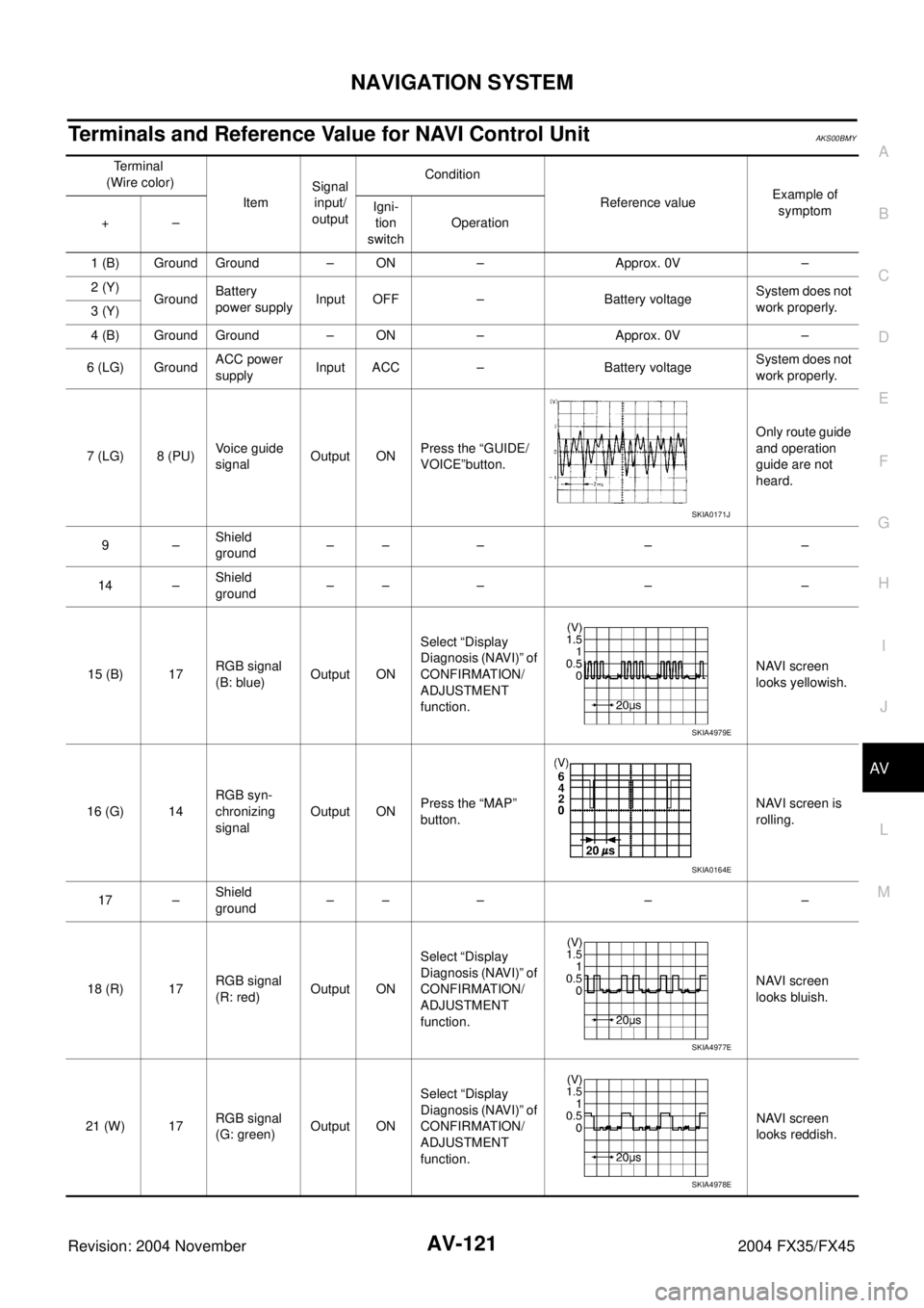
Terminals and Reference Value for NAVI Control UnitAKS00BMY
Terminal
(Wire color)
ItemSignal
input/
outputCondition
Reference valueExample of
symptom
+–Igni-
tion
switchOperation
1 (B) Ground Ground – ON – Approx. 0V –
2 (Y)
GroundBattery
power supplyInput OFF – Battery voltageSystem does not
work properly.
3 (Y)
4 (B) Ground Ground – ON – Approx. 0V –
6 (LG) GroundACC power
supplyInput ACC – Battery voltageSystem does not
work properly.
7 (LG) 8 (PU)Voice guide
signalOutput ONPress the “GUIDE/
VOICE”button.Only route guide
and operation
guide are not
heard.
9–Shield
ground–– – – –
14 –Shield
ground–– – – –
15 (B) 17RGB signal
(B: blue)Output ONSelect “Display
Diagnosis (NAVI)” of
CONFIRMATION/
ADJUSTMENT
function.NAVI screen
looks yellowish.
16 (G) 14RGB syn-
chronizing
signalOutput ONPress the “MAP”
button.NAVI screen is
rolling.
17 –Shield
ground–– – – –
18 (R) 17RGB signal
(R: red)Output ONSelect “Display
Diagnosis (NAVI)” of
CONFIRMATION/
ADJUSTMENT
function.NAVI screen
looks bluish.
21 (W) 17RGB signal
(G: green)Output ONSelect “Display
Diagnosis (NAVI)” of
CONFIRMATION/
ADJUSTMENT
function.NAVI screen
looks reddish.
SKIA0171J
SKIA4979E
SKIA0164E
SKIA4977E
SKIA4978E
Page 713 of 4449

AV-122
NAVIGATION SYSTEM
Revision: 2004 November 2004 FX35/FX45
25 (R) GroundIllumination
signalInput OFFLighting switch is
ON Approx. 12VNAVI control unit
illumination does
not change
when lighting
switch is turned
to 1st position. Lighting switch is
OFF Approx. 0V
26 (G) Ground Ignition signal Input ON – Battery voltageNavigation cur-
rent-location
mark does not
indicate the cor-
rect position.
27 (OR) GroundReverse
signalInput ONSelector lever in R
positionApprox. 12VThe navigation
current-location
mark moves
strangely when
the vehicle is
moving back-
wards. Selector lever
except R positionApprox. 0V
28 (GY) GroundVe h ic l e
speed signal
(8-pulse)Input ONWhen vehicle speed
is approx. 40 km/h
(25 MPH)Navigation cur-
rent-location
mark does not
indicate the cor-
rect position.
30 (BR) GroundIllumination
control signalInput OFF – Approx. 0V –
43 –Shield
ground–– – – –
44 (L) GroundCommunica-
tion signal (+)Input/
outputON –System does not
work properly.
45 (P) GroundCommunica-
tion signal (–)Input/
outputON –System does not
work properly.
66 67 GPS signal Input ONConnector is not
connected.Approx. 5VNavigation sys-
tem GPS correc-
tion is not
possible. Terminal
(Wire color)
ItemSignal
input/
outputCondition
Reference valueExample of
symptom
+–Igni-
tion
switchOperation
PKIA1935E
SKIA0175E
SKIA0176E
Page 714 of 4449

NAVIGATION SYSTEM
AV-123
C
D
E
F
G
H
I
J
L
MA
B
AV
Revision: 2004 November 2004 FX35/FX45
Terminals and Reference Value for Display Control UnitAKS00BMZ
Terminal
(Wire color)
ItemSignal
input/
outputCondition
Reference valueExample of
symptom
+–Igni-
tion
switchOperation
1 (W/L) GroundBattery
Power supplyInput OFF – Battery voltageSystem does not
work properly.
2 (W/G) GroundPower Sup-
ply (Inverter) Output ON – Approx. 9VScreen is not
shown
3 (B) Ground Ground – ON – Approx. 0V –
4 (BR/W) GroundPower Sup-
ply (Signal) Output ON – Approx. 9VScreen is not
shown
5 (P) Ground(Inverter)
Ground – ON – Approx. 0VScreen is not
shown
6 (OR) GroundReverse
signalInput ONSelector lever in R
positionApprox. 12V
Impossible to
gain direction of
vehicle. Selector lever
except R positionApprox. 0V
7 (P/L) Ground(Signal)
Ground – ON – Approx. 0V –
10 (LG/R) GroundACC power
supplyInput ACC – Battery voltageSystem does not
work properly.
12 (G/R) Ground Ignition signal Input ON – Battery voltageA/C operation is
not possible.
Vehicle informa-
tion setting is not
possible.
13 (B) Ground sysco – ON – Approx. 0V –
14 (R/L) GroundIllumination
signalInput OFFLighting switch is
ON.Approx. 12VAudio unit illumi-
nation does not
come on when
lighting switch is
ON. Lighting switch is
OFF.Approx. 0V
16 (R/G) GroundVehicle
speed signal
(8–pulse)Input ONWhen vehicle speed
is approx. 40 km/h
(25 MPH)Value of vehicle
information is
not accurately
displayed.
25 (L) – CAN H – – – – –
26 (R) – CAN L – – – – –
28 (B/R) GroundCommunica-
tion signal (+)Input/
OutputON –System does not
work properly.
29 –Shield
ground–– – – –
PKIA1935E
SKIA0175E
Page 720 of 4449

NAVIGATION SYSTEM
AV-129
C
D
E
F
G
H
I
J
L
MA
B
AV
Revision: 2004 November 2004 FX35/FX45
Terminals and Reference Value for A/C and AV SwitchAKS00BN1
Te r m i n a l
(Wire color)
ItemSignal
input/
outputCondition
Reference valueExample of
symptom
+–Igni-
tion
switchOperation
1 (W/L) GroundBattery power
supplyInput OFF – Battery voltageSystem does not
work properly.
2 (LG/R) GroundACC power
supplyInput ACC – Battery voltageSystem does not
work properly.
3 (R/L) GroundIllumination
signal Input OFFLighting switch is
ON.Approx. 12VA/C and AV
switch illumina-
tion does not
come on when
lighting switch is
ON. Turn lighting switch
OFF.Approx. 0V
4 (R/Y) GroundIllumination
control signalInput ONIllumination control
switch is operated
by lighting switch in
ON position.Chenges between approx. 0V
and approx. 12V A/C and AV
switch illumina-
tion does not
come on when
lighting switch is
ON.
5 (B) Ground Ground – ON – Approx. 0V –
6 (B/R) GroundCommunica-
tion signal (+)Input/
OutputON –System does not
work properly.
7–Shield
ground –– – – –
8 (W/R) GroundCommunica-
tion signal (–)Input/
OutputON –System does not
work properly.
SKIA0175E
SKIA0176E
Page 736 of 4449

NAVIGATION SYSTEM
AV-145
C
D
E
F
G
H
I
J
L
MA
B
AV
Revision: 2004 November 2004 FX35/FX45
Power Supply and Ground Circuit Check for NAVI Control UnitAKS00BN7
1. CHECK FUSE
Make sure that the following fuses of the NAVI control unit are not blown.
OK or NG
OK >> GO TO 2.
NG >> If fuse is blown, be sure to eliminate case of malfunction before installing new fuse. Refer to PG-3,
"POWER SUPPLY ROUTING CIRCUIT" .
2. CHECK POWER SUPPLY CIRCUIT
1. Check voltage between NAVI control unit harness connector ter-
minals and ground.
OK or NG
OK >> GO TO 3.
NG >> Repair harness or connector.
3. CHECK GROUND CIRCUIT
1. Turn ignition switch OFF.
2. Disconnect NAVI control unit connector.
3. Check continuity between NAVI control unit harness connector
B208 terminals 1 (B), 4 (B) and ground.
OK or NG
OK >> INSPECTION END
NG >> Repair harness or connector.
Unit Signal Fuse No.
NAVI control unitBattery power supply 32
ACC power supply 6
Terminals Ignition switch position
(+)
(–) OFF ACC ON
ConnectorTerminal
(Wire color)
B2082 (Y), 3 (Y)
GroundBattery
voltageBattery
voltageBattery
voltage
6 (LG) 0VBattery
voltageBattery
voltage
SKIA8932E
1, 4 – Ground : Continuity should exist.
PKIA2853E
Page 737 of 4449

AV-146
NAVIGATION SYSTEM
Revision: 2004 November 2004 FX35/FX45
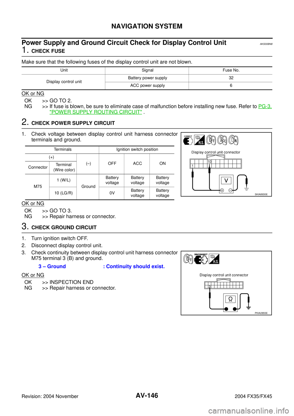
Power Supply and Ground Circuit Check for Display Control UnitAKS00BN8
1. CHECK FUSE
Make sure that the following fuses of the display control unit are not blown.
OK or NG
OK >> GO TO 2.
NG >> If fuse is blown, be sure to eliminate case of malfunction before installing new fuse. Refer to PG-3,
"POWER SUPPLY ROUTING CIRCUIT" .
2. CHECK POWER SUPPLY CIRCUIT
1. Check voltage between display control unit harness connector
terminals and ground.
OK or NG
OK >> GO TO 3.
NG >> Repair harness or connector.
3. CHECK GROUND CIRCUIT
1. Turn ignition switch OFF.
2. Disconnect display control unit.
3. Check continuity between display control unit harness connector
M75 terminal 3 (B) and ground.
OK or NG
OK >> INSPECTION END
NG >> Repair harness or connector.
Unit Signal Fuse No.
Display control unitBattery power supply 32
ACC power supply 6
Terminals Ignition switch position
(+)
(–) OFF ACC ON
ConnectorTerminal
(Wire color)
M751 (W/L)
GroundBattery
voltageBattery
voltageBattery
voltage
10 (LG/R) 0VBattery
voltageBattery
voltage
SKIA8930E
3 – Ground : Continuity should exist.
PKIA2855E
Page 740 of 4449

NAVIGATION SYSTEM
AV-149
C
D
E
F
G
H
I
J
L
MA
B
AV
Revision: 2004 November 2004 FX35/FX45
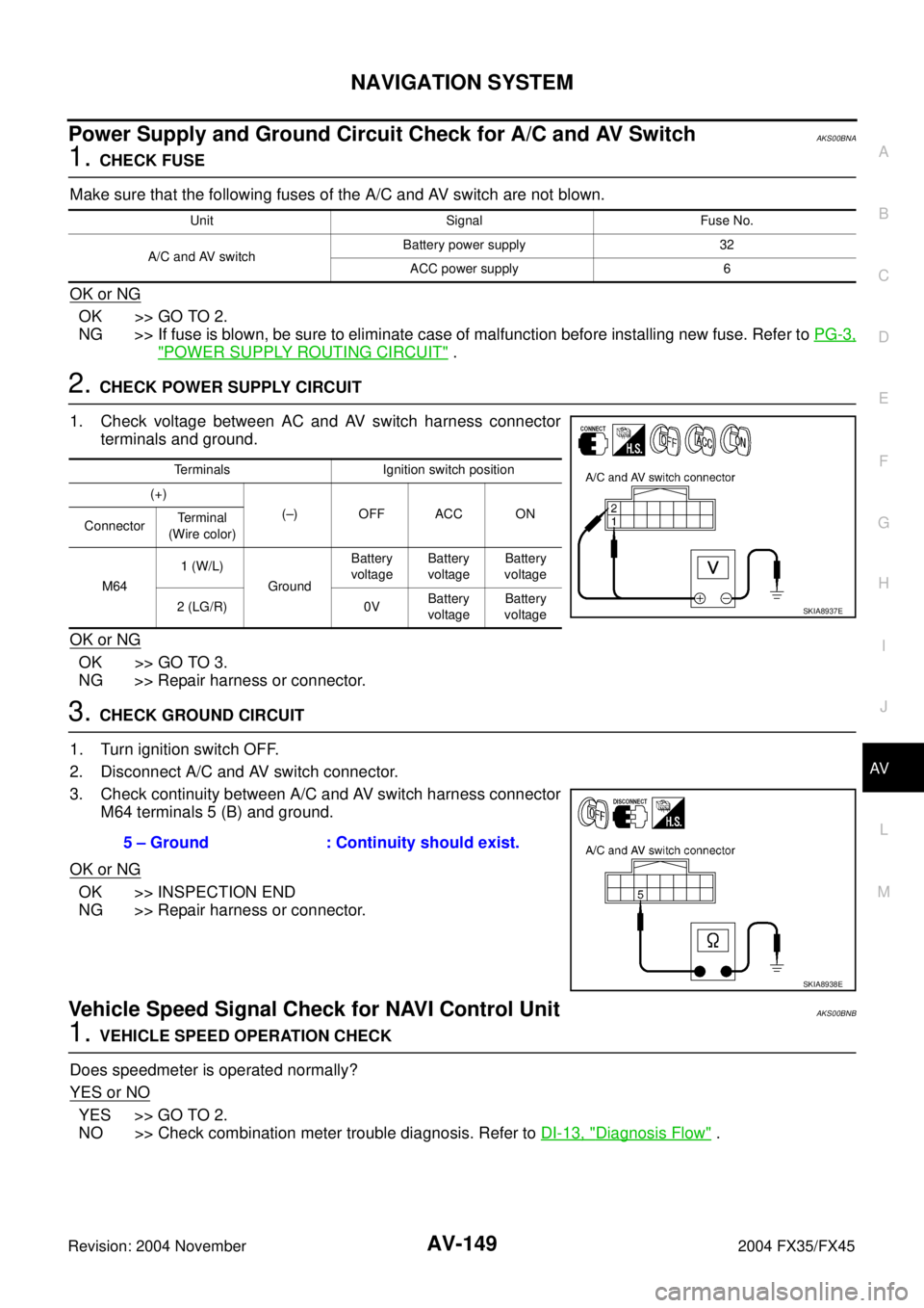
Power Supply and Ground Circuit Check for A/C and AV SwitchAKS00BNA
1. CHECK FUSE
Make sure that the following fuses of the A/C and AV switch are not blown.
OK or NG
OK >> GO TO 2.
NG >> If fuse is blown, be sure to eliminate case of malfunction before installing new fuse. Refer to PG-3,
"POWER SUPPLY ROUTING CIRCUIT" .
2. CHECK POWER SUPPLY CIRCUIT
1. Check voltage between AC and AV switch harness connector
terminals and ground.
OK or NG
OK >> GO TO 3.
NG >> Repair harness or connector.
3. CHECK GROUND CIRCUIT
1. Turn ignition switch OFF.
2. Disconnect A/C and AV switch connector.
3. Check continuity between A/C and AV switch harness connector
M64 terminals 5 (B) and ground.
OK or NG
OK >> INSPECTION END
NG >> Repair harness or connector.
Vehicle Speed Signal Check for NAVI Control UnitAKS00BNB
1. VEHICLE SPEED OPERATION CHECK
Does speedmeter is operated normally?
YES or NO
YES >> GO TO 2.
NO >> Check combination meter trouble diagnosis. Refer to DI-13, "
Diagnosis Flow" .
Unit Signal Fuse No.
A/C and AV switchBattery power supply 32
ACC power supply 6
Terminals Ignition switch position
(+)
(–) OFF ACC ON
ConnectorTe r m i n a l
(Wire color)
M641 (W/L)
GroundBattery
voltageBattery
voltageBattery
voltage
2 (LG/R) 0VBattery
voltageBattery
voltage
SKIA8937E
5 – Ground : Continuity should exist.
SKIA8938E