Page 337 of 4449

AT-260
ON-VEHICLE SERVICE
Revision: 2004 November 2004 FX35/FX45
Revolution Sensor Components (2WD Models Only)ACS007H2
COMPONENTS
REMOVAL
1. Disconnect the battery cable from the negative terminal.
2. Drain ATF through drain plug.
3. Remove front cross bar. Refer to FSU-8, "
Components" .
4. Remove exhaust front tube and center muffler with power tool. Refer to EX-3, "
Removal and Installation" .
5. Remove rear propeller shaft. Refer to PR-7, "
Removal and Installation" .
6. Remove oil pan and oil pan gasket.
7. Support transmission assembly with a transmission jack.
CAUTION:
When setting transmission jack, place wooden blocks to
prevent from damaging control valve with TCM and trans-
mission case.
8. Remove engine rear member with power tool. Refer to AT- 2 6 6 ,
"Removal and Installation (2WD Models)" .
1. Rear extension 2. Transmission 3. Revolution sensor
4. Oil pan gasket 5. Oil pan 6. Oil pan mounting bolt
7. Drain plug gasket 8. Drain plug 9. Self-sealing bolt
SCIA5145E
SCIA2308E
Page 340 of 4449

ON-VEHICLE SERVICE
AT-263
D
E
F
G
H
I
J
K
L
MA
B
AT
Revision: 2004 November 2004 FX35/FX45
6. Tighten rear extension assembly mounting bolts to specified
torque.
CAUTION:
Do not reuse self-sealing bolt.
7. Install engine rear member. Refer to AT- 2 6 6 , "
Removal and Installation (2WD Models)" .
8. Install oil pan to transmission case.
a. Install oil pan gasket to oil pan.
CAUTION:
�Do not reuse oil pan gasket.
�Install it in the direction to align hole positions.
�Complete remove all moisture, oil and old gasket, etc. from oil pan mounting surface.
b. Install oil pan (with oil pan gasket) to transmission case.
CAUTION:
�Install it so that drain plug comes to the position as
shown in the figure.
�Be careful not to pinch harnesses.
�Complete remove all moisture, oil and old gasket, etc.
from oil pan mounting surface.
c. Tighten oil pan mounting bolts to the specified torque in numeri-
cal order as shown in the figure after temporarily tightening
them.
CAUTION:
Do not reuse oil pan mounting bolts.
9. Install drain plug to oil pan.
CAUTION:
Do not reuse drain plug gasket.
10. Install rear propeller shaft. Refer to PR-7, "
Removal and Installation" .
11. Install exhaust front tube and center muffler. Refer to EX-3, "
Removal and Installation" .
12. Install front cross bar. Refer to FSU-8, "
Components" .
13. Pour ATF into transmission assembly. Refer to AT- 1 2 , "
Changing A/T Fluid" .
14. Connect the battery cable to the negative terminal.Rear extension assembly mounting bolt
: 52 N·m (5.3 Kg-m, 38 ft-lb)
Self-sealing bolt
: 61 N·m (6.2 Kg-m, 45 ft-lb)
SCIA3426E
SCIA2308E
: 7.9 N·m (0.81 kg-m, 70 in-lb)
: 34 N·m (3.5 kg-m, 25 ft-lb)
SCIA2492E
Page 343 of 4449

AT-266
TRANSMISSION ASSEMBLY
Revision: 2004 November 2004 FX35/FX45
TRANSMISSION ASSEMBLYPFP:31020
Removal and Installation (2WD Models)ACS002S1
COMPONENTS
REMOVAL
CAUTION:
When removing the A/T assembly from engine, first remove the crankshaft position sensor (POS) from
the A/T assembly.
Be careful not to damage sensor edge.
1. Disconnect the battery cable from the negative terminal.
2. Remove engine cover.
3. Remove A/T fluid level gauge.
4. Remove engine under cover with power tool.
5. Remove front cross bar. Refer to FSU-8, "
Components" .
6. Remove exhaust front tube and center muffler with power tool. Refer to EX-3, "
Removal and Installation" .
7. Remove three way catalyst. Refer to EM-26, "
Removal and Installation" .
8. Remove rear propeller shaft. Refer to PR-7, "
Removal and Installation" .
9. Remove control rod. Refer to AT- 2 3 3 , "
Control Device Removal and Installation" .
1. Transmission assembly 2. A/T fluid charging pipe 3. O-ring
4. Fluid cooler tube 5. Copper washer 6. A/T fluid level gauge
7. Engine rear member 8. Insulator
SCIA5050E
Page 347 of 4449

AT-270
TRANSMISSION ASSEMBLY
Revision: 2004 November 2004 FX35/FX45
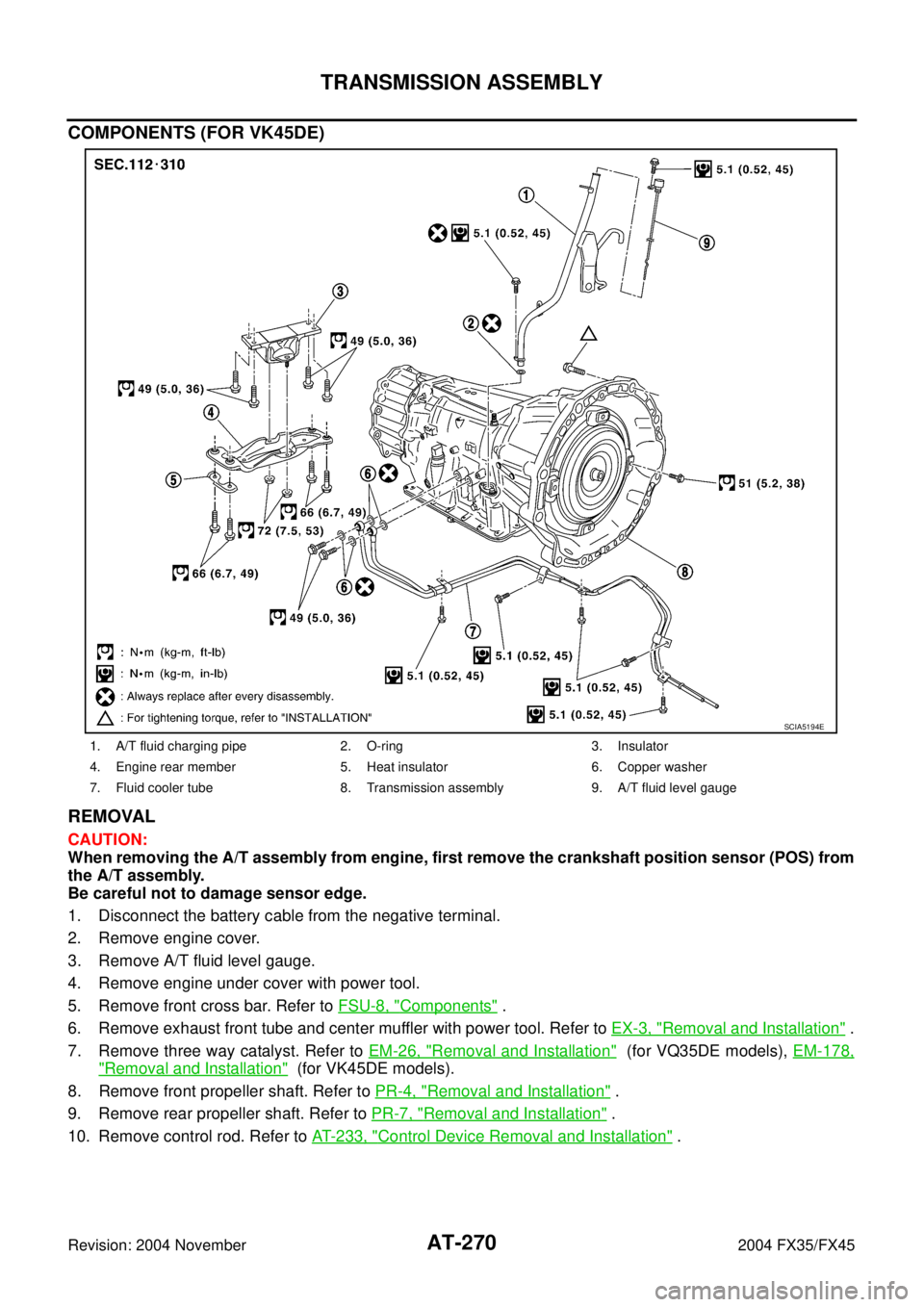
COMPONENTS (FOR VK45DE)
REMOVAL
CAUTION:
When removing the A/T assembly from engine, first remove the crankshaft position sensor (POS) from
the A/T assembly.
Be careful not to damage sensor edge.
1. Disconnect the battery cable from the negative terminal.
2. Remove engine cover.
3. Remove A/T fluid level gauge.
4. Remove engine under cover with power tool.
5. Remove front cross bar. Refer to FSU-8, "
Components" .
6. Remove exhaust front tube and center muffler with power tool. Refer to EX-3, "
Removal and Installation" .
7. Remove three way catalyst. Refer to EM-26, "
Removal and Installation" (for VQ35DE models), EM-178,
"Removal and Installation" (for VK45DE models).
8. Remove front propeller shaft. Refer to PR-4, "
Removal and Installation" .
9. Remove rear propeller shaft. Refer to PR-7, "
Removal and Installation" .
10. Remove control rod. Refer to AT- 2 3 3 , "
Control Device Removal and Installation" .
1. A/T fluid charging pipe 2. O-ring 3. Insulator
4. Engine rear member 5. Heat insulator 6. Copper washer
7. Fluid cooler tube 8. Transmission assembly 9. A/T fluid level gauge
SCIA5194E
Page 448 of 4449

PREPARATION
ATC-19
C
D
E
F
G
H
I
K
L
MA
B
AT C
Revision: 2004 November 2004 FX35/FX45
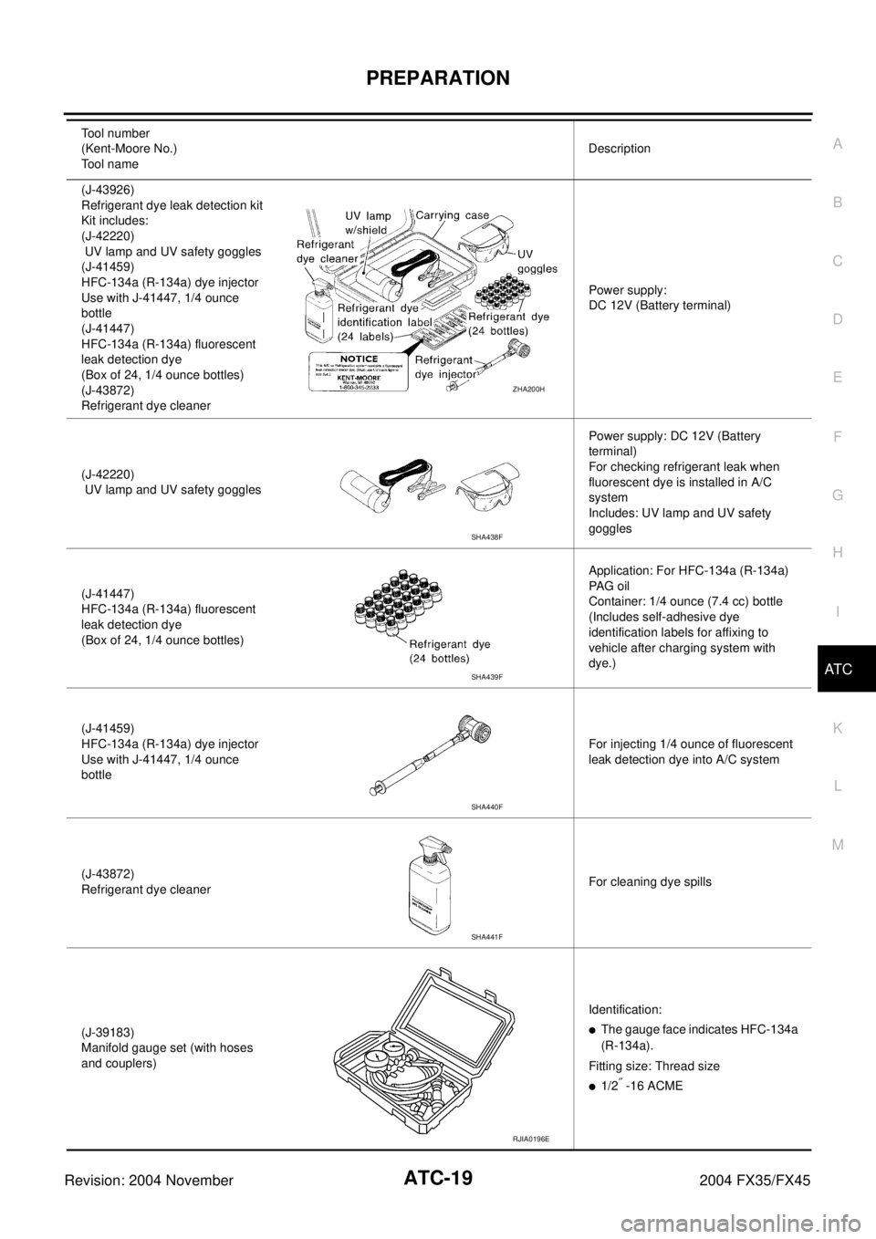
(J-43926)
Refrigerant dye leak detection kit
Kit includes:
(J-42220)
UV lamp and UV safety goggles
(J-41459)
HFC-134a (R-134a) dye injector
Use with J-41447, 1/4 ounce
bottle
(J-41447)
HFC-134a (R-134a) fluorescent
leak detection dye
(Box of 24, 1/4 ounce bottles)
(J-43872)
Refrigerant dye cleanerPower supply:
DC 12V (Battery terminal)
(J-42220)
UV lamp and UV safety gogglesPower supply: DC 12V (Battery
terminal)
For checking refrigerant leak when
fluorescent dye is installed in A/C
system
Includes: UV lamp and UV safety
goggles
(J-41447)
HFC-134a (R-134a) fluorescent
leak detection dye
(Box of 24, 1/4 ounce bottles)Application: For HFC-134a (R-134a)
PA G o i l
Container: 1/4 ounce (7.4 cc) bottle
(Includes self-adhesive dye
identification labels for affixing to
vehicle after charging system with
dye.)
(J-41459)
HFC-134a (R-134a) dye injector
Use with J-41447, 1/4 ounce
bottleFor injecting 1/4 ounce of fluorescent
leak detection dye into A/C system
(J-43872)
Refrigerant dye cleanerFor cleaning dye spills
(J-39183)
Manifold gauge set (with hoses
and couplers)Identification:
�The gauge face indicates HFC-134a
(R-134a).
Fitting size: Thread size
�1/2″ -16 ACME Tool number
(Kent-Moore No.)
Tool name Description
ZHA200H
SHA438F
SHA439F
SHA440F
SHA441F
RJIA0196E
Page 480 of 4449
TROUBLE DIAGNOSIS
ATC-51
C
D
E
F
G
H
I
K
L
MA
B
AT C
Revision: 2004 November 2004 FX35/FX45
Auto Amp. Terminals and Reference ValueAJS0014O
Measure voltage between each terminal and ground by following ter-
minals and reference value for unified meter and A/C amp.
PIN CONNECTOR TERMINAL LAYOUT
TERMINALS AND REFERENCE VALUE FOR UNIFIED METER AND A/C AMP.
RJIA1965E
RJIA1966E
Terminal
No.Wire
colorItemIgnition
switchConditionVoltage
(V)
1 L CAN H - - -
11 R C A N L - - -
21 R/W Power supply for BATT OFF - Battery voltage
22 G/R Power supply for IGN ON - Battery voltage
29 B Ground (Power) ON - Approx. 0
30 B Ground ON - Approx. 0
35 LG/R Power supply for ACC ON - Battery voltage
39 Y Ambient sensor - - -
40 BR/W In-vehicle sensor - - -
41 P Intake sensor - - -
42 R/Y Compressor ON signal ONA/C switch: ON Approx. 0
A/C switch: OFF Approx. 5
43 G/B A/C LAN signal ON -
45 PU/WECV (Electric Control Valve)
signalON -
HAK0652D
RJIA1606E
Page 481 of 4449
ATC-52
TROUBLE DIAGNOSIS
Revision: 2004 November 2004 FX35/FX45
46 L/W Power supply for IGN2 ON - Battery voltage
49 W/G Sensor ground ON - Approx. 0
50 LG Sunload sensor - - -
53 G Blower motor control signal ON Blower speed: 1st step
54 Y/RPower supply for each door
motorON - Battery voltage
57 BR/Y Blower motor ON signal ONA/C switch: ON (Blower motor
operate)Approx. 0
A/C switch: OFF Approx. 5 Te r m i n a l
No.Wire
colorItemIgnition
switchConditionVoltag e
(V)
SJIA0116J
Page 483 of 4449

ATC-54
TROUBLE DIAGNOSIS
Revision: 2004 November 2004 FX35/FX45
FUNCTION CONFIRMATION PROCEDURE
1. SET IN SELF-DIAGNOSTIC MODE
1. Turn ignition switch ON.
2. Set in self-diagnostic mode as follows. Within 10 seconds after starting engine (ignition switch is turned
ON.), press OFF switch for at least 5 seconds.
CAUTION:
�If battery voltage drops below 12V during diagnosis STEP-3, actuator speed becomes slower and
as a result, the system may generate an error even when operation is usual. To avoid this, start
engine before performing this diagnosis.
�Former STEP-1 (LEDs and display screen are checked) does not exist in this self-diagnosis func-
tion.
>> GO TO 2.
2. STEP-2: SENSOR CIRCUITS ARE CHECKED FOR OPEN OR SHORT CIRCUIT
Does code No. 20 appear on the display?
YES >> GO TO 3.
NO >> GO TO 13.
3. CHECK TO ADVANCE SELF-DIAGNOSIS STEP-3
Press temperature (UP) switch (driver side).
Advance to self
-diagnosis STEP-3?
YES >> GO TO 4.
NO >> Malfunctioning OFF switch or unified meter and A/C amp. Refer to ATC-102, "
Self-diagnosis" .
4. CHECK TO RETURN SELF-DIAGNOSIS STEP-2
Press temperature (DOWN) switch (driver side).
Return to self
-diagnosis STEP-2?
YES >> GO TO 5.
NO >> Replace A/C and AV switch. Temperature switch malfunctions.
5. STEP-3: MODE DOOR AND INTAKE DOOR POSITIONS ARE CHECKED
Press temperature (UP) switch (driver side).
Does code No. 30 appear on the display?
YES >> GO TO 6.
NO >> GO TO 14.
RJIA0219E
RJIA0220E