Page 877 of 4449

BL-70
REMOTE KEYLESS ENTRY SYSTEM
Revision: 2004 November 2004 FX35/FX45
Panic alarm (horn and headlamp) does not activate
when panic alarm button is continuously pressed.1. Check panic alarm mode.*
*: Panic alarm mode can be changed.
First check the panic alarm setting.BL-67
2. Check key fob battery and function.BL-71
3. Check headlamp function.BL-79
4. Check horn function.BL-79
5. Check IPDM E/R operation.BL-78
6. Check key switch.BL-77
7. Replace key fob. Refer to ID Code Entry Procedure.
NOTE:
If the result of key fob function check with CONSULT-II is OK, key
fob is not malfunctioning.BL-80
8. Replace BCM.BCS-15
Auto door lock operation does not activate properly.
(All other remote keyless entry system function is
OK.)1. Check auto door lock operation mode.*
*: Auto door lock operation mode can be changed.
First check the auto door lock operation setting.BL-67
2. Replace BCM.BCS-15
Keyless power window down (open) operation does
not activate properly.
(All other remote keyless entry system function is
OK.)1. Check power window down operation mode.*
*: Power window down operation mode can be changed.
First check the power window down setting.BL-67
2. Check power window function.GW-15
3. Replace BCM.BCS-15
Map lamp and ignition keyhole illumination opera-
tion does not activate properly.1. Check map lamp and ignition keyhole illumination operation.BL-792. Check door switch.BL-73
3. Replace BCM.BCS-15
Symptom Diagnoses/service procedureReference
page
Page 878 of 4449

REMOTE KEYLESS ENTRY SYSTEM
BL-71
C
D
E
F
G
H
J
K
L
MA
B
BL
Revision: 2004 November 2004 FX35/FX45
Check Key Fob Battery and FunctionAIS004MK
1. CHECK KEY FOB BATTERY
1. Remove key fob battery. Refer to BL-83, "
Key Fob Battery Replacement" .
2. Measure voltage between battery positive and negative termi-
nals, (+) and (−).
NOTE:
Key fob does not function if battery is not set correctly.
OK or NG
OK >> GO TO 2.
NG >> Replace battery.
2. CHECK KEY FOB FUNCTION
With CONSULT-II
Check key fob function in “DATA MONITOR” mode with CONSULT-
II. When pushing each button of key fob, the corresponding monitor
item should be turned as follows.
OK or NG
OK >> Key fob is OK.
NG >> Replace key fob.Voltage : 2.5 – 3.0V
SEL237W
Condition Monitor item
Pushing LOCK KEYLESS LOCK : ON
Pushing UNLOCK KEYLESS UNLOCK : ON
Keep pushing UNLOCKRKE KEEP UNLK : ON
*: UN BUTTON ON turns to ON three sec-
onds after UNLOCK button keeps pushing.
Pushing PANIC KEYLESS PANIC : ON
Pushing LOCK and UNLOCK at the
same timeRKE LCK-UNLOCK : ON
PIIA6468E
Page 879 of 4449
BL-72
REMOTE KEYLESS ENTRY SYSTEM
Revision: 2004 November 2004 FX35/FX45
Check ACC SwitchAIS004ML
1. CHECK ACC SWITCH
With CONSULT-II
Check ACC switch (“ACC ON SW”) in “DATA MONITOR” mode with
CONSULT-II.
Without CONSULT-II
Check voltage between BCM connector and ground.
OK or NG
OK >> ACC switch is OK.
NG >> Check the following.
�10A fuse [No. 6, located in fuse block (J/B)]
�Harness for open or short between BCM and fuse.
Monitor item Condition
ACC SWIgnition switch position is ACC or ON : ON
Ignition switch position is OFF : OFF
PIIA3367E
Item(+)
(–) ConditionVoltage (V)
Approx. Con-
nectorTerminal
(Wire color)
BCM M3 11 (LG/R) GroundACC or ON Battery voltage
OFF 0
PIIA7002E
Page 880 of 4449
REMOTE KEYLESS ENTRY SYSTEM
BL-73
C
D
E
F
G
H
J
K
L
MA
B
BL
Revision: 2004 November 2004 FX35/FX45
Check Door SwitchAIS004MM
CHECK DOOR SWITCH (EXCEPT BACK DOOR SWITCH)
1. CHECK DOOR SWITCH INPUT SIGNAL
With CONSULT-II
Check door switches (“DOOR SW-DR”, “DOOR SW-AS”, “DOOR
SW-RL” and “DOOR SW-RR”) in “DATA MONITOR” mode with
CONSULT-II.
Without CONSULT-II
Check voltage between BCM connector and ground.
OK or NG
OK >> Door switch circuit is OK.
NG >> GO TO 2.
Monitor item Condition
DOOR SW-DR
CLOSE → OPEN: OFF → ON DOOR SW-AS
DOOR SW-RL
DOOR SW-RR
Item ConnectorTerminals
(Wire color)Door
conditionVoltage (V)
(Approx.)
(+) (-)
Driver side
B1462 (W)
GroundCLOSE
↓
OPENBattery voltage
↓
0 Rear LH 63 (P)
Passenger side
M312 (P/B)
Rear RH 13 (P/L)
PIIA6469E
PIIA7003E
Page 884 of 4449

REMOTE KEYLESS ENTRY SYSTEM
BL-77
C
D
E
F
G
H
J
K
L
MA
B
BL
Revision: 2004 November 2004 FX35/FX45
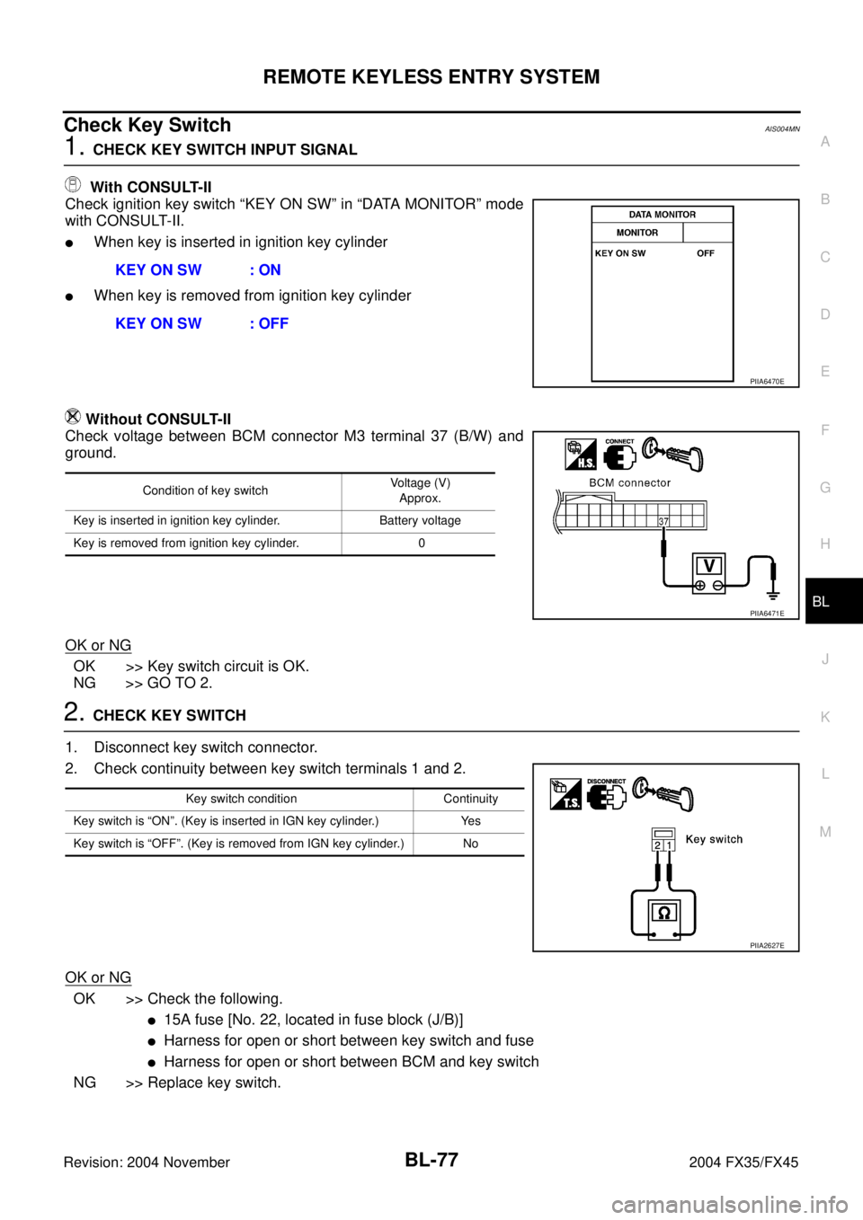
Check Key SwitchAIS004MN
1. CHECK KEY SWITCH INPUT SIGNAL
With CONSULT-II
Check ignition key switch “KEY ON SW” in “DATA MONITOR” mode
with CONSULT-II.
�When key is inserted in ignition key cylinder
�When key is removed from ignition key cylinder
Without CONSULT-II
Check voltage between BCM connector M3 terminal 37 (B/W) and
ground.
OK or NG
OK >> Key switch circuit is OK.
NG >> GO TO 2.
2. CHECK KEY SWITCH
1. Disconnect key switch connector.
2. Check continuity between key switch terminals 1 and 2.
OK or NG
OK >> Check the following.
�15A fuse [No. 22, located in fuse block (J/B)]
�Harness for open or short between key switch and fuse
�Harness for open or short between BCM and key switch
NG >> Replace key switch.KEY ON SW : ON
KEY ON SW : OFF
PIIA6470E
Condition of key switchVoltage (V)
Approx.
Key is inserted in ignition key cylinder. Battery voltage
Key is removed from ignition key cylinder. 0
PIIA6471E
Key switch condition Continuity
Key switch is “ON”. (Key is inserted in IGN key cylinder.) Yes
Key switch is “OFF”. (Key is removed from IGN key cylinder.) No
PIIA2627E
Page 885 of 4449
BL-78
REMOTE KEYLESS ENTRY SYSTEM
Revision: 2004 November 2004 FX35/FX45
Check IPDM E/R OperationAIS004MO
1. CHECK IPDM E/R INPUT VOLTAGE
Check voltage between IPDM E/R connector E9 terminal 51 and
ground.
OK or NG
OK >> Replace IPDM E/R.
NG >> GO TO 2.
2. CHECK IPDM E/R HARNESS
1. Turn ignition switch OFF.
2. Disconnect IPDM E/R and horn relay connector.
3. Check continuity between IPDM E/R connector E9 terminal 51
and horn relay connector E10 terminal 1.
OK or NG
OK >> Check harness connection.
NG >> Repair or replace harness.51 (SB) – Ground : Battery voltage
PIIA6403E
51 (SB) – 1 (SB) : Continuity should exist.
PIIA6404E
Page 890 of 4449

REMOTE KEYLESS ENTRY SYSTEM
BL-83
C
D
E
F
G
H
J
K
L
MA
B
BL
Revision: 2004 November 2004 FX35/FX45
NOTE:
�If a key fob is lost, the ID code of the lost key fob must be erased to prevent unauthorized use. A specific
ID code can be erased with CONSULT-II. However, when the ID code of a lost key fob is not known, all
controller ID codes should be erased. After all ID codes are erased, the ID codes of all remaining and/or
new key fobs must be re-registered.
To erase all ID codes in memory, register one ID code (key fob) five times. After all ID codes are erased,
the ID codes of all remaining and/or new key fobs must be re-registered.
�When registering an additional key fob, the existing ID codes in memory may or may not be erased. If five
ID codes are stored in memory, when an additional code is registered, only the oldest code is erased. If
less than five ID codes are stored in memory, when an additional ID code is registered, the new ID code is
added and no ID codes are erased.
�If you need to activate more than two additional new key fobs, repeat the procedure “Additional ID code
entry” for each new key fob.
�Entry of maximum five ID codes is allowed. When more than five ID codes are entered, the oldest ID code
will be erased.
�Even if same ID code that is already in the memory is input, the same ID code can be entered. The code
is counted as an additional code.
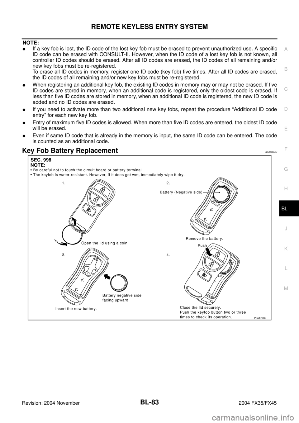
Key Fob Battery ReplacementAIS004MU
PIIA4706E
Page 893 of 4449

BL-86
INTELLIGENT KEY SYSTEM
Revision: 2004 November 2004 FX35/FX45
System DescriptionAIS004MW
�The Intelligent Key system is a system which can lock and unlock the doors (door lock function) and start
the engine (engine start function) by carrying around the Intelligent Key, which operates based on the
results of electrical key-ID verification using two-way communications between the Intelligent Key and the
vehicle
�Operation of the remote control buttons on the Intelligent Key also provides the same functions as the
remote control entry system. (Remote control entry functions)
�As an ignition key warning function, when a door is locked or unlocked with entry switch or remote control-
ler button operation, the hazard lamps flash and the Intelligent Key warning buzzer sounds.
�Even if the vehicle or Intelligent Key battery runs down, the door can be locked and unlocked and the
engine started with the mechanical key built into the Intelligent Key.
�If an Intelligent Key was lost, a new Intelligent Key can be registered. A maximum of 4 Intelligent Keys can
be registered.
�It has been made possible to diagnose the system, change the function setting and register an Intelligent
Key with the CONSULT-II.
DOOR LOCK FUNCTION
Operation Description
�When the driver door, passenger door, or back door request switch is pressed, Intelligent Key unit sends a
request signal from the transmission antenna corresponding to the pressed door request switch, key-ID
verification is performed using two-way communication with Intelligent Key, and if ID is successfully veri-
fied, a door lock/unlock request signal is sent to BCM (Body Control Module) using CAN communication
to lock/unlock the door lock.
�When door is locking, door is unlocked, when door is unlocking, door is locked.
�When door is locked/unlocked by door request switch operation, hazard lamps flash and Intelligent Key
warning buzzer sounds.
�With the locking operation of door request switch, door lock actuators of all door are locked.
Driver side door request switch operation
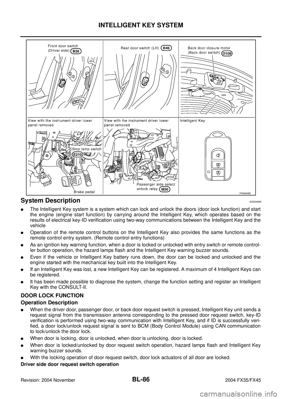
PIIA6648E