Page 1 of 4449

ABCDEFGHIJKMLQUICK REFERENCE INDEX AGENERAL INFORMATIONGIGeneral InformationBENGINEEMEngine MechanicalLUEngine Lubrication SystemCOEngine Cooling SystemECEngine Control SystemFLFuel SystemEXExhaust SystemACCAccelerator Control SystemCTRANSMISSION/
TRANSAXLEATAutomatic TransmissionDDRIVELINE/AXLETFTransferPRPropeller ShaftFFDFront Final DriveRFDRear Final DriveFAXFront AxleRAXRear AxleESUSPENSIONFSUFront SuspensionRSURear SuspensionWTRoad Wheels & TiresFBRAKESBRBrake SystemPBParking Brake SystemBRCBrake Control SystemGSTEERINGPSPower Steering SystemHRESTRAINTSSBSeat BeltsSRSSupplemental Restraint System
(SRS)IBODYBLBody, Lock & Security SystemGWGlasses, Window System & Mir-
rorsRFRoofEIExterior & InteriorIPInstrument PanelSESeatJAIR CONDITIONERATCAutomatic Air ConditionerKELECTRICALSCStarting & Charging SystemLTLighting SystemDIDriver Information SystemWWWiper, Washer & HornBCSBody Control SystemLANLAN SystemAVAudio Visual, Navigation & Tele-
phone SystemACSAuto Cruise Control SystemPGPower Supply, Ground & Circuit Ele-
mentsLMAINTENANCEMAMaintenanceMINDEXIDXAlphabetical IndexEdition: July 2003
Revision: November 2004
Page 16 of 4449
![INFINITI FX35 2004 Service Manual DESCRIPTION
ACS-7
[ICC]
C
D
E
F
G
H
I
J
L
MA
B
ACS
Revision: 2004 November 2004 FX35/FX45
Components DescriptionAKS006YD
CAN CommunicationAKS00815
CAN (Controller Area Network) is a serial communicati](/manual-img/42/57021/w960_57021-15.png "INFINITI FX35 2004 Service Manual DESCRIPTION
ACS-7
[ICC]
C
D
E
F
G
H
I
J
L
MA
B
ACS
Revision: 2004 November 2004 FX35/FX45
Components DescriptionAKS006YD
CAN CommunicationAKS00815
CAN (Controller Area Network) is a serial communicati")
DESCRIPTION
ACS-7
[ICC]
C
D
E
F
G
H
I
J
L
MA
B
ACS
Revision: 2004 November 2004 FX35/FX45
Components DescriptionAKS006YD
CAN CommunicationAKS00815
CAN (Controller Area Network) is a serial communication line for real time application. It is an on-vehicle mul-
tiplex communication line with high data communication speed and excellent error detection ability. Many elec-
tric control units are equipped onto a vehicle, and each control unit shares information and links with other
control units during operation (not independent). In CAN communication, control units are connected with 2
communication lines (CAN H line, CAN L line) allowing a high rate of information transmission with less wiring.
Each control unit transmits/receives data but selectively reads required data only.
CAN COMMUNICATION UNIT
Refer to LAN-6, "CAN Communication Unit" .
Switch OperationAKS006YF
The system is operated by a master ON/OFF switch and four control switches, all mounted on the steering
wheel.
ComponentVe h i -
cle-to-
vehi-
cle dis-
tance
con-
trol
modeCon-
ven-
tional
(fixed
speed)
cruise
con-
trol
modeBrake
assist
(with
pre-
view
brake)Description
ICC unit×××Operates throttle control actuator and brake booster based on that sensor
signals and CAN communication data, then controls vehicle distance.
ICC sensor××Irradiate laser beam, and receives reflected laser beam to measure dis-
tance from preceding vehicle.
ECM××Transmits throttle position signal and ICC steering switch signal to ICC unit.
ABS actuator and electric
unit (control unit)×××Transmits wheel speed signal to ICC unit.
Brake pressure sensor××Detects fluid pressure in master cylinder.
Brake booster××Adjusts brake fluid pressure, based on command from ICC unit.
BCM×Transmit front wiper request signal to ICC unit.
TCM××Transmits gear position signal and output shaft revolution signal to ICC
unit.
SKIA5973E
Page 88 of 4449
PREPARATION
AT-11
D
E
F
G
H
I
J
K
L
MA
B
AT
Revision: 2004 November 2004 FX35/FX45
Commercial Service ToolsACS0079Y
Tool nameDescription
Power toolLoosening bolts and nuts
Drift
a: 22mm (0.87 in) dia.Installing manual shaft oil seals
Drift
a: 64 mm (2.52 in) dia.Installing rear oil seal (AWD models)
PBIC0190E
NT083
SCIA5338E
Page 94 of 4449
A/T CONTROL SYSTEM
AT-17
D
E
F
G
H
I
J
K
L
MA
B
AT
Revision: 2004 November 2004 FX35/FX45
A/T CONTROL SYSTEMPFP:31036
Cross-Sectional View (2WD Models)ACS002LD
1. Front planetary gear 2. Mid planetary gear 3. Rear planetary gear
4. Direct clutch 5. High and low reverse clutch 6. Reverse brake
7. Drum support 8. Forward brake 9. Low coast brake
10. Input shaft 11. Torque converter 12. Oil pump
13. Front brake 14. 3rd one-way clutch 15. Input clutch
16. 1st one-way clutch 17. Control valve with TCM 18. Forward one-way clutch
19. Rear extension 20. Output shaft
SCIA5262E
Page 95 of 4449
AT-18
A/T CONTROL SYSTEM
Revision: 2004 November 2004 FX35/FX45
Cross-Sectional View (AWD Models)ACS0033B
1. Front planetary gear 2. Mid planetary gear 3. Rear planetary gear
4. Direct clutch 5. High and low reverse clutch 6. Reverse brake
7. Drum support 8. Forward brake 9. Low coast brake
10. Input shaft 11. Torque converter 12. Oil pump
13. Front brake 14. 3rd one-way clutch 15. Input clutch
16. 1st one-way clutch 17. Control valve with TCM 18. Forward one-way clutch
19. Adapter case 20. Output shaft
SCIA5263E
Page 96 of 4449

A/T CONTROL SYSTEM
AT-19
D
E
F
G
H
I
J
K
L
MA
B
AT
Revision: 2004 November 2004 FX35/FX45
Shift MechanismACS002LE
The automatic transmission uses compact triple planetary gear systems to improve power-transmission effi-
ciency, simplify construction and reduce weight.
It also employs an optimum shift control and super wide gear ratios. They improve starting performance and
acceleration during medium and high-speed operation.
CONSTRUCTION
FUNCTION OF CLUTCH AND BRAKE
1. Front brake 2. Input clutch 3. Direct clutch
4. High and low reverse clutch 5. Reverse brake 6. Forward brake
7. Low coast brake 8. 1st one-way clutch 9. Forward one-way clutch
10. 3rd one-way clutch 11. Front sun gear 12. Input shaft
13. Mid internal gear 14. Front internal gear 15. Rear carrier
16. Rear sun gear 17. Mid sun gear 18. Front carrier
19. Mid carrier 20. Rear internal gear 21. Output shaft
22. Parking gear 23. Parking pawl
PCIA0002J
Name of the Part Abbreviation Function
Front brake (1) FR/B Fastens the front sun gear (11).
Input clutch (2) I/CConnects the input shaft (12), the front internal gear (14) and the mid internal
gear (13).
Direct clutch (3) D/C Connects the rear carrier (15) and the rear sun gear (16).
High and low reverse clutch (4) HLR/C Connects the mid sun gear (17) and the rear sun gear (16).
Reverse brake (5) R/B Fastens the rear carrier (15).
Forward brake (6) Fwd/B Fastens the mid sun gear (17).
Low coast brake (7) LC/B Fastens the mid sun gear (17).
1st one-way clutch (8) 1st/owcAllows the rear sun gear (16) to turn freely forward relative to the mid sun gear
(17) but fastens it for reverse rotation.
Forward one-way clutch (9) F/owcAllows the mid sun gear (17) to turn freely in the forward direction but fastens it
for reverse rotation.
3rd one-way clutch (10) 3rd/owcAllows the front sun gear (11) to turn freely in the forward direction but fastens
it for reverse rotation.
Page 98 of 4449

A/T CONTROL SYSTEM
AT-21
D
E
F
G
H
I
J
K
L
MA
B
AT
Revision: 2004 November 2004 FX35/FX45
POWER TRANSMISSION
“N” Position
Since both the forward brake and the reverse brake are released, torque from the input shaft drive is not trans-
mitted to the output shaft.
“P” Position
�The same as for the “N” position, both the forward brake and the reverse brake are released, so torque
from the input shaft drive is not transmitted to the output shaft.
�The parking pawl linked with the selector lever meshes with the parking gear and fastens the output shaft
mechanically.
1. Front brake 2. Input clutch 3. Direct clutch
4. High and low reverse clutch 5. Reverse brake 6. Forward brake
7. Low coast brake 8. 1st one-way clutch 9. Forward one-way clutch
10. 3rd one-way clutch 11. Front sun gear 12. Input shaft
13. Mid internal gear 14. Front internal gear 15. Rear carrier
16. Rear sun gear 17. Mid sun gear 18. Front carrier
19. Mid carrier 20. Rear internal gear 21. Output shaft
22. Parking gear 23. Parking pawl
PCIA0003J
Page 99 of 4449
AT-22
A/T CONTROL SYSTEM
Revision: 2004 November 2004 FX35/FX45
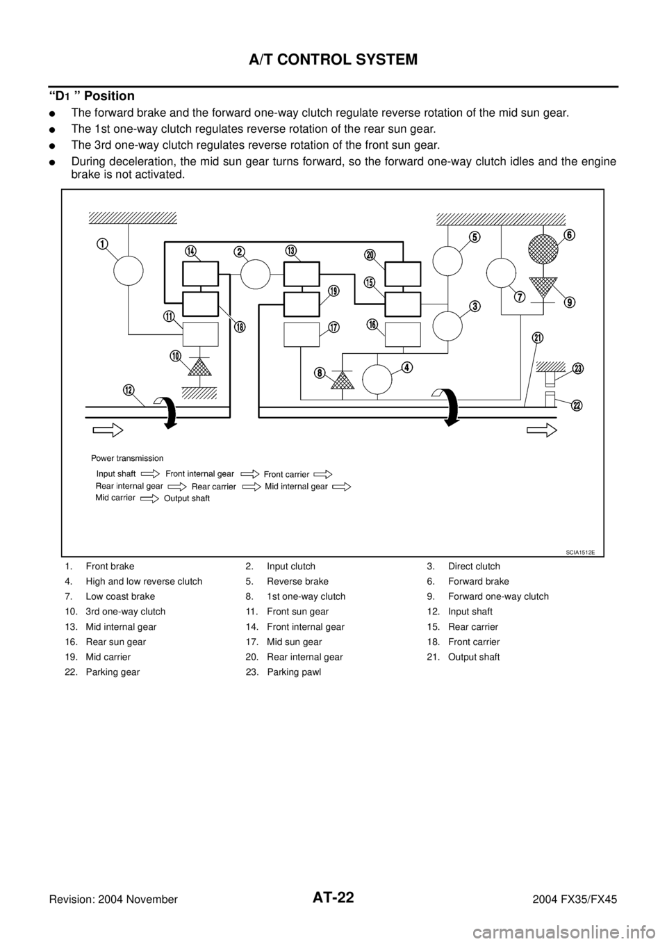
“D1 ” Position
�The forward brake and the forward one-way clutch regulate reverse rotation of the mid sun gear.
�The 1st one-way clutch regulates reverse rotation of the rear sun gear.
�The 3rd one-way clutch regulates reverse rotation of the front sun gear.
�During deceleration, the mid sun gear turns forward, so the forward one-way clutch idles and the engine
brake is not activated.
1. Front brake 2. Input clutch 3. Direct clutch
4. High and low reverse clutch 5. Reverse brake 6. Forward brake
7. Low coast brake 8. 1st one-way clutch 9. Forward one-way clutch
10. 3rd one-way clutch 11. Front sun gear 12. Input shaft
13. Mid internal gear 14. Front internal gear 15. Rear carrier
16. Rear sun gear 17. Mid sun gear 18. Front carrier
19. Mid carrier 20. Rear internal gear 21. Output shaft
22. Parking gear 23. Parking pawl
SCIA1512E
 dia.")
ACS002LD
1. Front planetary gear 2. Mid planetary")
ACS0033B
1. Front planetary gear 2. Mid planetary gear 3. Rear planetary gear
4. Direct clutch 5. High")