Page 100 of 4449
A/T CONTROL SYSTEM
AT-23
D
E
F
G
H
I
J
K
L
MA
B
AT
Revision: 2004 November 2004 FX35/FX45
“M1” Position
�The front brake fastens the front sun gear.
�The forward brake and the forward one-way clutch regulate reverse rotation of the mid sun gear.
�High and low reverse clutch connects the rear sun gear and the mid sun gear.
�The low coast brake fastens the mid sun gear.
�During deceleration, the low coast brake regulates forward rotation of the mid sun gear and the engine
brake functions.
1. Front brake 2. Input clutch 3. Direct clutch
4. High and low reverse clutch 5. Reverse brake 6. Forward brake
7. Low coast brake 8. 1st one-way clutch 9. Forward one-way clutch
10. 3rd one-way clutch 11. Front sun gear 12. Input shaft
13. Mid internal gear 14. Front internal gear 15. Rear carrier
16. Rear sun gear 17. Mid sun gear 18. Front carrier
19. Mid carrier 20. Rear internal gear 21. Output shaft
22. Parking gear 23. Parking pawl
SCIA1513E
Page 101 of 4449
AT-24
A/T CONTROL SYSTEM
Revision: 2004 November 2004 FX35/FX45
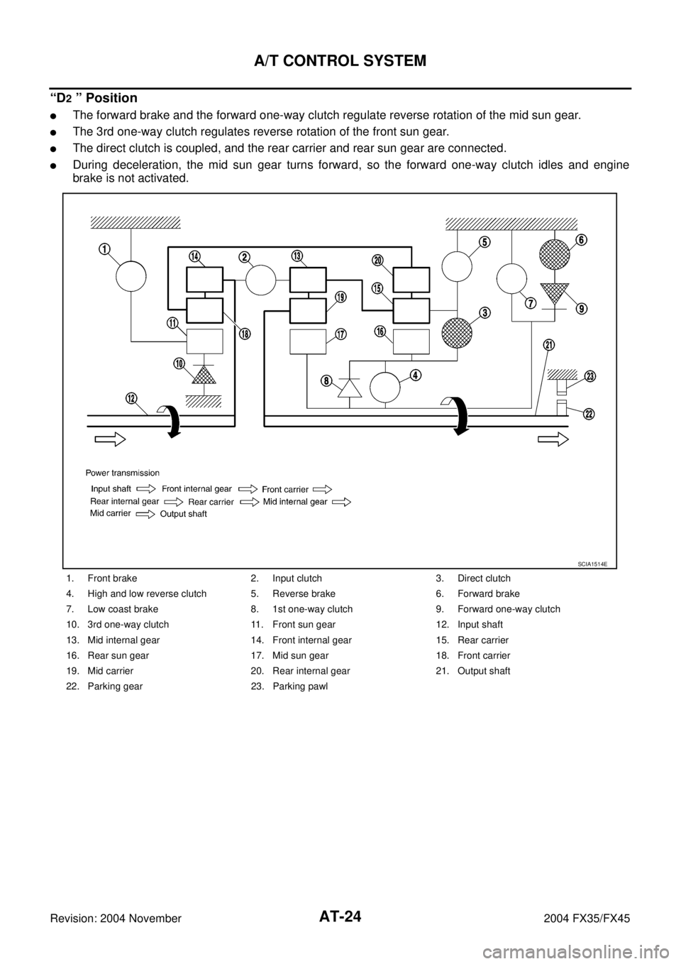
“D2 ” Position
�The forward brake and the forward one-way clutch regulate reverse rotation of the mid sun gear.
�The 3rd one-way clutch regulates reverse rotation of the front sun gear.
�The direct clutch is coupled, and the rear carrier and rear sun gear are connected.
�During deceleration, the mid sun gear turns forward, so the forward one-way clutch idles and engine
brake is not activated.
1. Front brake 2. Input clutch 3. Direct clutch
4. High and low reverse clutch 5. Reverse brake 6. Forward brake
7. Low coast brake 8. 1st one-way clutch 9. Forward one-way clutch
10. 3rd one-way clutch 11. Front sun gear 12. Input shaft
13. Mid internal gear 14. Front internal gear 15. Rear carrier
16. Rear sun gear 17. Mid sun gear 18. Front carrier
19. Mid carrier 20. Rear internal gear 21. Output shaft
22. Parking gear 23. Parking pawl
SCIA1514E
Page 102 of 4449
A/T CONTROL SYSTEM
AT-25
D
E
F
G
H
I
J
K
L
MA
B
AT
Revision: 2004 November 2004 FX35/FX45
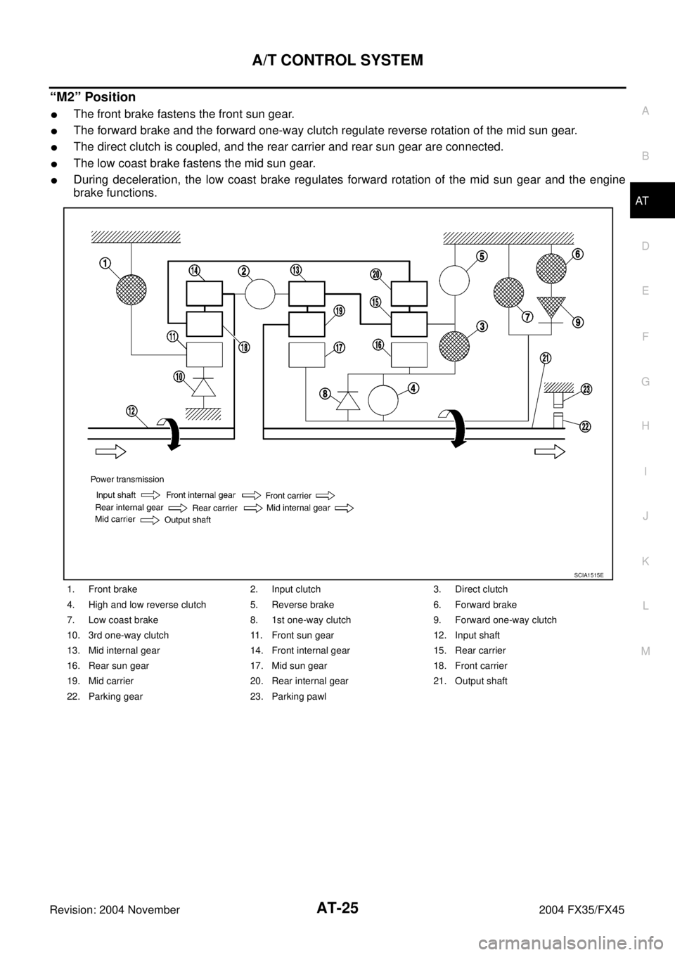
“M2” Position
�The front brake fastens the front sun gear.
�The forward brake and the forward one-way clutch regulate reverse rotation of the mid sun gear.
�The direct clutch is coupled, and the rear carrier and rear sun gear are connected.
�The low coast brake fastens the mid sun gear.
�During deceleration, the low coast brake regulates forward rotation of the mid sun gear and the engine
brake functions.
1. Front brake 2. Input clutch 3. Direct clutch
4. High and low reverse clutch 5. Reverse brake 6. Forward brake
7. Low coast brake 8. 1st one-way clutch 9. Forward one-way clutch
10. 3rd one-way clutch 11. Front sun gear 12. Input shaft
13. Mid internal gear 14. Front internal gear 15. Rear carrier
16. Rear sun gear 17. Mid sun gear 18. Front carrier
19. Mid carrier 20. Rear internal gear 21. Output shaft
22. Parking gear 23. Parking pawl
SCIA1515E
Page 103 of 4449
AT-26
A/T CONTROL SYSTEM
Revision: 2004 November 2004 FX35/FX45
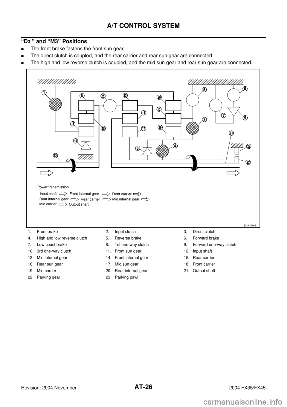
“D3 ” and “M3” Positions
�The front brake fastens the front sun gear.
�The direct clutch is coupled, and the rear carrier and rear sun gear are connected.
�The high and low reverse clutch is coupled, and the mid sun gear and rear sun gear are connected.
1. Front brake 2. Input clutch 3. Direct clutch
4. High and low reverse clutch 5. Reverse brake 6. Forward brake
7. Low coast brake 8. 1st one-way clutch 9. Forward one-way clutch
10. 3rd one-way clutch 11. Front sun gear 12. Input shaft
13. Mid internal gear 14. Front internal gear 15. Rear carrier
16. Rear sun gear 17. Mid sun gear 18. Front carrier
19. Mid carrier 20. Rear internal gear 21. Output shaft
22. Parking gear 23. Parking pawl
SCIA1516E
Page 104 of 4449

A/T CONTROL SYSTEM
AT-27
D
E
F
G
H
I
J
K
L
MA
B
AT
Revision: 2004 November 2004 FX35/FX45
“D4 ” and “M4” Positions
�The direct clutch is coupled, and the rear carrier and rear sun gear are connected.
�The high and low reverse clutch is coupled, and the mid sun gear and rear sun gear are connected.
�The input clutch is coupled, and the front internal gear and mid internal gear are connected.
�The drive power is conveyed to the front internal gear, mid internal gear, and rear carrier and the three
planetary gears rotate forward as one unit.
1. Front brake 2. Input clutch 3. Direct clutch
4. High and low reverse clutch 5. Reverse brake 6. Forward brake
7. Low coast brake 8. 1st one-way clutch 9. Forward one-way clutch
10. 3rd one-way clutch 11. Front sun gear 12. Input shaft
13. Mid internal gear 14. Front internal gear 15. Rear carrier
16. Rear sun gear 17. Mid sun gear 18. Front carrier
19. Mid carrier 20. Rear internal gear 21. Output shaft
22. Parking gear 23. Parking pawl
SCIA1517E
Page 105 of 4449
AT-28
A/T CONTROL SYSTEM
Revision: 2004 November 2004 FX35/FX45
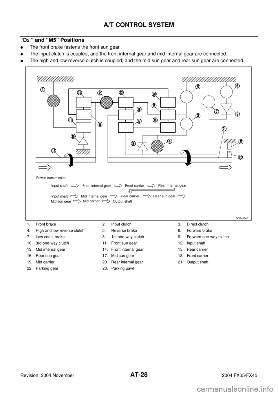
“D5 ” and “M5” Positions
�The front brake fastens the front sun gear.
�The input clutch is coupled, and the front internal gear and mid internal gear are connected.
�The high and low reverse clutch is coupled, and the mid sun gear and rear sun gear are connected.
1. Front brake 2. Input clutch 3. Direct clutch
4. High and low reverse clutch 5. Reverse brake 6. Forward brake
7. Low coast brake 8. 1st one-way clutch 9. Forward one-way clutch
10. 3rd one-way clutch 11. Front sun gear 12. Input shaft
13. Mid internal gear 14. Front internal gear 15. Rear carrier
16. Rear sun gear 17. Mid sun gear 18. Front carrier
19. Mid carrier 20. Rear internal gear 21. Output shaft
22. Parking gear 23. Parking pawl
SCIA4984E
Page 106 of 4449
A/T CONTROL SYSTEM
AT-29
D
E
F
G
H
I
J
K
L
MA
B
AT
Revision: 2004 November 2004 FX35/FX45
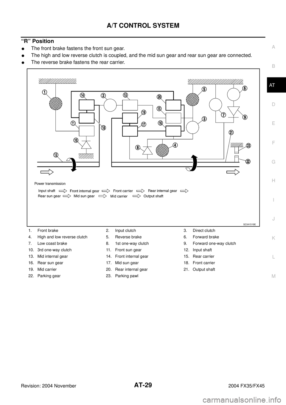
“R” Position
�The front brake fastens the front sun gear.
�The high and low reverse clutch is coupled, and the mid sun gear and rear sun gear are connected.
�The reverse brake fastens the rear carrier.
1. Front brake 2. Input clutch 3. Direct clutch
4. High and low reverse clutch 5. Reverse brake 6. Forward brake
7. Low coast brake 8. 1st one-way clutch 9. Forward one-way clutch
10. 3rd one-way clutch 11. Front sun gear 12. Input shaft
13. Mid internal gear 14. Front internal gear 15. Rear carrier
16. Rear sun gear 17. Mid sun gear 18. Front carrier
19. Mid carrier 20. Rear internal gear 21. Output shaft
22. Parking gear 23. Parking pawl
SCIA1519E
Page 129 of 4449

AT-52
TROUBLE DIAGNOSIS
Revision: 2004 November 2004 FX35/FX45
CAUTION:
Run the engine at idle for at least one minute.
Judgement Stall Test
O: Stall speed within standard value position
H: Stall speed higher than standard value
L: Stall speed lower than standard value
Stall test standard value position
LINE PRESSURE TEST
Line Pressure Test Port
Line Pressure Test Procedure
1. Inspect the amount of engine oil and replenish if necessary.
2. Drive the car for about 10 minutes to warm it up so that the A/T fluid reaches in range of 50 to 80°C (122
to 176°F), then inspect the amount of A/T fluid and replenish if necessary.
NOTE:
The A/T fluid temperature rises in range of 50 to 80°C (122 to 176°F) during 10 minutes of driving.
3. Remove front propeller shaft from vehicle (with AWD models). Refer to PR-4, "
Removal and Installation" . Stall speed:
VQ35DE engine: 2,650 - 2,950 rpm
VK45DE engine: 2,300 - 2,600 rpm
Selector lever position
Expected problem location
D, M R
Stall speedHO
�Forward brake
�Forward one-way clutch
�1st one-way clutch
�3rd one-way clutch
OH
�Reverse brake
LL
�Engine and torque converter one-way clutch
HH
�Line pressure low
Does not shift up D, M position 1 → 2 Slipping in 2nd, 3rd, 4th gears Direct clutch slippage
Does not shift up D, M position 2 → 3 Slipping in 3rd, 4th, 5th gears high and low reverse clutch slippage
Does not shift up D, M position 3 → 4 Slipping in 4th, 5th gears Input clutch slippage
Does not shift up D, M position 4 → 5 Slipping in 5th gear Front brake slippage
SCIA2187E