Page 295 of 4449

AT-218
TROUBLE DIAGNOSIS FOR SYMPTOMS
Revision: 2004 November 2004 FX35/FX45
9. CHECK TCM
1. Check TCM input/output signals. Refer to AT- 9 0 , "
TCM Input/Output Signal Reference Values" .
2. If NG, recheck A/T assembly harness connector terminals for damage or loose connection with harness
connector.
OK or NG
OK >>INSPECTION END
NG >> Repair or replace damaged parts.
10. DETECT MALFUNCTIONING ITEM
�Check the malfunction items. If any items are damaged, repair or replace damaged parts. Refer to AT- 6 5 ,
"Symptom Chart" (Symptom No.24).
OK or NG
OK >> GO TO 8.
NG >> Repair or replace damaged parts.
A/T Does Not Hold Lock-up ConditionACS007GQ
SYMPTOM:
The lock-up condition cannot be maintained for more than 30 seconds.
DIAGNOSTIC PROCEDURE
1. CHECK SELF-DIAGNOSTIC RESULTS
Perform self-diagnosis. Refer to AT- 9 4 , "
SELF-DIAGNOSTIC RESULT MODE" , AT- 1 0 3 , "TCM SELF-DIAG-
NOSTIC PROCEDURE (NO TOOLS)" .
Do the self-diagnostic results indicate torque converter clutch solenoid valve, engine speed signal, turbine rev-
olution sensor, CAN communication?
YES >> Check the malfunctioning system. Refer to AT- 1 2 3 , "DTC P0740 TORQUE CONVERTER
CLUTCH SOLENOID VALVE" , AT- 1 2 1 , "DTC P0725 ENGINE SPEED SIGNAL" , AT- 1 4 3 , "DTC
P1716 TURBINE REVOLUTION SENSOR" , AT- 1 0 5 , "DTC U1000 CAN COMMUNICATION
LINE" .
NO >> GO TO 2.
2. CHECK A/T FLUID LEVEL
Check A/T fluid level. Refer to AT- 1 2 , "
Checking A/T Fluid" .
OK or NG
OK >> GO TO 3.
NG >> Refill ATF.
SAT638A
Page 297 of 4449

AT-220
TROUBLE DIAGNOSIS FOR SYMPTOMS
Revision: 2004 November 2004 FX35/FX45
Lock-up Is Not ReleasedACS007GR
SYMPTOM:
The lock-up condition cannot be cancelled even after releasing the accelerator pedal.
DIAGNOSTIC PROCEDURE
1. CHECK SELF-DIAGNOSTIC RESULTS
Perform self-diagnosis. Refer to AT- 9 4 , "
SELF-DIAGNOSTIC RESULT MODE" , AT- 1 0 3 , "TCM SELF-DIAG-
NOSTIC PROCEDURE (NO TOOLS)" .
Do the self-diagnostic results indicate torque converter clutch solenoid valve, engine speed signal, turbine rev-
olution sensor, CAN communication?
YES >> Check the malfunctioning system. Refer to AT- 1 2 3 , "DTC P0740 TORQUE CONVERTER
CLUTCH SOLENOID VALVE" , AT- 1 2 1 , "DTC P0725 ENGINE SPEED SIGNAL" , AT- 1 4 3 , "DTC
P1716 TURBINE REVOLUTION SENSOR" , AT- 1 0 5 , "DTC U1000 CAN COMMUNICATION
LINE" .
NO >> GO TO 2.
2. CHECK SYMPTOM
Check again. Refer to AT- 5 7 , "
Cruise Test - Part 1" .
OK or NG
OK >>INSPECTION END
NG >> GO TO 3.
3. CHECK TCM
1. Check TCM input/output signals. Refer to AT- 9 0 , "
TCM Input/Output Signal Reference Values" .
2. If NG, recheck A/T assembly harness connector terminals for damage or loose connection with harness
connector.
OK or NG
OK >>INSPECTION END
NG >> Repair or replace damaged parts.
Page 310 of 4449
SHIFT CONTROL SYSTEM
AT-233
D
E
F
G
H
I
J
K
L
MA
B
AT
Revision: 2004 November 2004 FX35/FX45
SHIFT CONTROL SYSTEMPFP:34901
Control Device Removal and InstallationACS002RQ
1. Selector lever knob 2. Lock pin 3. Knob cover
4. A/T device harness connector 5. Shift lock solenoid and park position
switch assembly6. Bracket
7. Control rod 8. Plain washer 9. Conical washer
10. Snap pin 11. Dust cover 12. Dust cover plate
13. Control device assembly 14. Position lamp 15. Position indicator plate
SCIA4846E
Page 311 of 4449

AT-234
SHIFT CONTROL SYSTEM
Revision: 2004 November 2004 FX35/FX45
REMOVAL
1. Disconnect lower lever of control device and control rod.
2. Remove knob cover below selector lever downward.
3. Pull lock pin out of selector lever knob.
4. Remove selector lever knob.
5. Remove console finisher.
�Refer to IP-10, "Component Parts Drawing" .
6. Remove center console.
�Refer to IP-10, "Component Parts Drawing" .
7. Remove key interlock cable from control device.
�Refer to AT- 2 4 0 , "Removal and Installation" .
8. Disconnect A/T device harness connector.
9. Remove control device assembly.
INSTALLATION
Install in reverse order of removal. Be careful of the following:
�After installation is completed, adjust and check A/T position.
Adjustment of A/T PositionACS002RR
1. Loosen nut of control rod.
2. Place PNP switch and selector lever in “P” position.
3. While pressing lower lever toward rear of vehicle (in P position
direction), tighten nut to specified torque.
CAUTION:
Do not push the bracket.
Checking of A/T PositionACS002RS
1. Place selector lever in “P” position, and turn ignition switch ON (Do not start engine).
2. Make sure selector lever can be shifted to other than “P” position when brake pedal is depressed. Also
make sure selector lever can be shifted from “P” position only when brake pedal is depressed.
3. Move the selector lever and check for excessive effort, sticking, noise or rattle.
4. Confirm the selector lever stops at each position with the feel of engagement when it is moved through all
the positions. Check whether or not the actual position the selector lever is in matches the position shown
by the shift position indicator and the transmission body.
5. The method of operating the lever to individual positions cor-
rectly should be as shown in the figure.
6. When selector button is pressed in “P”, “R”, or “N” position with-
out applying forward/backward force to selector lever, check but-
ton operation for sticking.
7. Confirm the back-up lamps illuminate only when lever is placed
in the “R” position. Confirm the back-up lamps does not illumi-
nate when selector lever is pushed against “R” position in the
“P” or “N” position.
8. Confirm the engine can only be started with the selector lever in
the “P” and “N” positions.
9. Make sure transmission is locked completely in “P” position.
10. When selector lever is set to manual shift gate, make sure manual mode is displayed on combination
meter.
Shift selector lever to “+” and “-” sides, and make sure set shift position changes.
SCIA4954E
:26 N·m (2.7 kg-m, 19 ft-lb)
SCIA2119E
SCIA3906E
Page 312 of 4449
A/T SHIFT LOCK SYSTEM
AT-235
D
E
F
G
H
I
J
K
L
MA
B
AT
Revision: 2004 November 2004 FX35/FX45
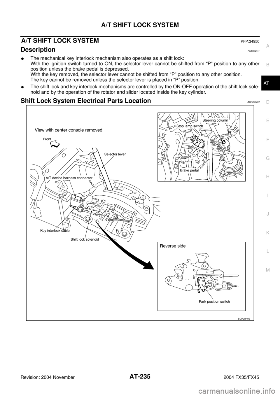
A/T SHIFT LOCK SYSTEMPFP:34950
DescriptionACS002RT
�The mechanical key interlock mechanism also operates as a shift lock:
With the ignition switch turned to ON, the selector lever cannot be shifted from “P” position to any other
position unless the brake pedal is depressed.
With the key removed, the selector lever cannot be shifted from “P” position to any other position.
The key cannot be removed unless the selector lever is placed in “P” position.
�The shift lock and key interlock mechanisms are controlled by the ON-OFF operation of the shift lock sole-
noid and by the operation of the rotator and slider located inside the key cylinder.
Shift Lock System Electrical Parts LocationACS002RU
SCIA2149E
Page 313 of 4449
AT-236
A/T SHIFT LOCK SYSTEM
Revision: 2004 November 2004 FX35/FX45
Wiring Diagram — AT — SHIFTACS002RV
TCWM0149E
Page 314 of 4449

A/T SHIFT LOCK SYSTEM
AT-237
D
E
F
G
H
I
J
K
L
MA
B
AT
Revision: 2004 November 2004 FX35/FX45
Diagnostic ProcedureACS002RW
SYMPTOM 1:
�Selector lever cannot be moved from “P” position with key in ON position and brake pedal
applied.
�Selector lever can be moved from “P” position with key in ON position and brake pedal released.
�Selector lever can be moved from “P” position when key is removed from key cylinder.
SYMPTOM 2:
�Ignition key cannot be removed when selector lever is set to “P” position.
�Ignition key can be removed when selector lever is set to any position except “P” position.
1. CHECK KEY INTERLOCK CABLE
Check the key interlock cable for damage.
OK or NG
OK >> GO TO 2.
NG >> Repair key interlock cable. Refer to AT- 2 3 9 , "
KEY INTERLOCK CABLE" .
2. CHECK SELECTOR LEVER POSITION
Check the selector lever position for damage.
OK or NG
OK >> GO TO 3.
NG >> Adjustment control linkage. Refer to AT- 2 3 4 , "
Adjustment of A/T Position" .
3. CHECK SHIFT LOCK SOLENOID AND PARK POSITION SWITCH
1. Connect A/T device harness connector.
2. Turn ignition switch “ON”.
3. Selector lever is set in “P” position.
4. Check operation sound.
OK or NG
OK >>INSPECTION END
NG >> GO TO 4.
4. CHECK POWER SOURCE
1. Turn ignition switch “ON”. (Do not start engine.)
2. Check the voltage between A/T device harness connector M67
terminal 1(G/R) and ground. Refer to AT- 2 3 6 , "
Wiring Diagram
— AT — SHIFT" .
OK or NG
OK >> GO TO 7.
NG >> GO TO 5.
Condition Brake pedal Operation sound
When ignition switch is turned to
“ON” position and selector lever
is set in “P” position.Depressed Yes
Released No
Condition Brake pedal Data (Approx.)
When ignition switch is turned to
“ON” position.Depressed Battery voltage
Released 0V
SCIA2122E
Page 315 of 4449

AT-238
A/T SHIFT LOCK SYSTEM
Revision: 2004 November 2004 FX35/FX45
5. CHECK STOP LAMP SWITCH
1. Turn ignition switch “OFF”.
2. Disconnect stop lamp switch harness connector.
3. Check continuity between stop lamp switch harness connector
E210 terminals 3(G) and 4(OR). Refer to AT- 2 3 6 , "
Wiring Dia-
gram — AT — SHIFT" .
Check stop lamp switch after adjusting brake pedal — refer to
BR-6, "
BRAKE PEDAL" .
OK or NG
OK >> GO TO 6.
NG >> Repair or replace damaged parts.
6. DETECT MALFUNCTIONING ITEM
Check the following items. If any items are damaged, repair or replace damaged parts.
�Harness for short or open between ignition switch and stop lamp switch harness terminal 3(G).
�Harness for short or open between stop lamp switch harness terminal 4(O/R) and A/T device harness ter-
minal 1(G/R).
�10A fuse [No.12, located in the fuse block (J/B)].
�Ignition switch. Refer to PG-3, "POWER SUPPLY ROUTING CIRCUIT" .
OK or NG
OK >>INSPECTION END
NG >> Repair or replace damaged parts.
7. CHECK GROUND CIRCUIT
1. Turn ignition switch “OFF”.
2. Disconnect A/T device harness connector.
3. Check continuity between A/T device harness connector M67
terminal 2(B) and ground.
4. Connect A/T device harness connector.
OK or NG
OK >> Replace shift lock solenoid or park position switch
assembly.
NG >> Repair open circuit or short to ground or short to power
in harness or connectors.
Condition Continuity
When brake pedal is depressed Yes
When brake pedal is released No
SCIA2126E
Continuity should exist.
SCIA2125E