Page 2749 of 4449
EM-24
[VQ35DE]
INTAKE MANIFOLD
Revision: 2004 November 2004 FX35/FX45
INTAKE MANIFOLDPFP:14003
Removal and InstallationABS004U3
REMOVAL
1. Release fuel pressure. Refer to EC-51, "FUEL PRESSURE RELEASE" .
2. Remove intake manifold collector (upper and lower). Refer to EM-19, "
INTAKE MANIFOLD COLLECTOR"
.
3. Remove fuel tube and fuel injector assembly. Refer to EM-45, "
FUEL INJECTOR AND FUEL TUBE" .
4. Loosen bolts and nuts in reverse order of illustration to remove
intake manifold with power tool.
5. Remove intake manifold gaskets.
CAUTION:
Cover engine openings to avoid entry of foreign materials.
INSPECTION AFTER REMOVAL
Surface Distortion
�Check the surface distortion of the intake manifold mating sur-
face with straightedge and feeler gauge.
�If it exceeds the limit, replace intake manifold.
1. Harness bracket 2. Intake manifold 3. Gasket
SBIA0487E
PBIC0778E
Limit : 0.1 mm (0.04 in)
PBIC0870E
Page 2760 of 4449
OIL PAN AND OIL STRAINER
EM-35
[VQ35DE]
C
D
E
F
G
H
I
J
K
L
MA
EM
Revision: 2004 November 2004 FX35/FX45
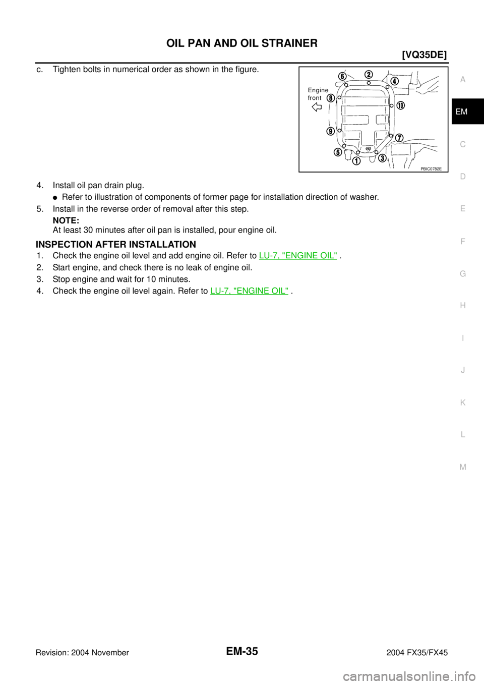
c. Tighten bolts in numerical order as shown in the figure.
4. Install oil pan drain plug.
�Refer to illustration of components of former page for installation direction of washer.
5. Install in the reverse order of removal after this step.
NOTE:
At least 30 minutes after oil pan is installed, pour engine oil.
INSPECTION AFTER INSTALLATION
1. Check the engine oil level and add engine oil. Refer to LU-7, "ENGINE OIL" .
2. Start engine, and check there is no leak of engine oil.
3. Stop engine and wait for 10 minutes.
4. Check the engine oil level again. Refer to LU-7, "
ENGINE OIL" .
PBIC0782E
Page 2766 of 4449
![INFINITI FX35 2004 Service Manual OIL PAN AND OIL STRAINER
EM-41
[VQ35DE]
C
D
E
F
G
H
I
J
K
L
MA
EM
Revision: 2004 November 2004 FX35/FX45
4. Install oil pan (lower) in the order below.
a. Apply liquid gasket thoroughly with tube pres](/manual-img/42/57021/w960_57021-2765.png "INFINITI FX35 2004 Service Manual OIL PAN AND OIL STRAINER
EM-41
[VQ35DE]
C
D
E
F
G
H
I
J
K
L
MA
EM
Revision: 2004 November 2004 FX35/FX45
4. Install oil pan (lower) in the order below.
a. Apply liquid gasket thoroughly with tube pres")
OIL PAN AND OIL STRAINER
EM-41
[VQ35DE]
C
D
E
F
G
H
I
J
K
L
MA
EM
Revision: 2004 November 2004 FX35/FX45
4. Install oil pan (lower) in the order below.
a. Apply liquid gasket thoroughly with tube presser [SST:
WS39930000 ( – )] as in illustration.
Use Genuine RTV Silicone Sealant or equivalent. Refer to
GI-48, "
RECOMMENDED CHEMICAL PRODUCTS AND
SEALANTS" .
NOTE:
Attaching should be done within 5 minutes after coating.
b. Tighten bolts in numerical order as shown in the figure.
5. Install oil pan drain plug.
�Refer to illustration of components of former page for installation direction of washer.
6. Install in the reverse order of removal after this step.
NOTE:
At least 30 minutes after oil pan is installed, pour engine oil.
INSPECTION AFTER INSTALLATION
1. Check the engine oil level and add engine oil. Refer to LU-7, "ENGINE OIL" .
2. Start engine, and check there is no leak of engine oil.
3. Stop engine and wait for 10 minutes.
4. Check the engine oil level again. Refer to LU-7, "
ENGINE OIL" .
PBIC1146E
PBIC0782E
Page 2773 of 4449
![INFINITI FX35 2004 Service Manual EM-48
[VQ35DE]
FUEL INJECTOR AND FUEL TUBE
Revision: 2004 November 2004 FX35/FX45
�Lubricate O-ring with new engine oil.
�Do not clean O-ring with solvent.
�Make sure that O-ring and its mating part a](/manual-img/42/57021/w960_57021-2772.png "INFINITI FX35 2004 Service Manual EM-48
[VQ35DE]
FUEL INJECTOR AND FUEL TUBE
Revision: 2004 November 2004 FX35/FX45
�Lubricate O-ring with new engine oil.
�Do not clean O-ring with solvent.
�Make sure that O-ring and its mating part a")
EM-48
[VQ35DE]
FUEL INJECTOR AND FUEL TUBE
Revision: 2004 November 2004 FX35/FX45
�Lubricate O-ring with new engine oil.
�Do not clean O-ring with solvent.
�Make sure that O-ring and its mating part are free of foreign material.
�When installing O-ring, be careful not to scratch it with tool or fingernails. Also be careful not
to twist or stretch O-ring. If O-ring was stretched while it was being attached, do not insert it
quickly into fuel tube.
�Insert O-ring straight into fuel tube. Do not decenter or twist it.
�Insert fuel damper and fuel sub-tube straight into fuel tube.
�Tighten mounting bolts evenly in turn.
�After tightening mounting bolts, make sure that there is no gap between flange and fuel tube.
2. Install O-rings to fuel injector paying attention to the items below.
CAUTION:
�Upper and lower O-ring are different. Be careful not to confuse them.
�Handle O-ring with bare hands. Never wear gloves.
�Lubricate O-ring with new engine oil.
�Do not clean O-ring with solvent.
�Make sure that O-ring and its mating part are free of foreign material.
�When installing O-ring, be careful not to scratch it with tool or fingernails. Also be careful not to
twist or stretch O-ring. If O-ring was stretched while it was being attached, do not insert it
quickly into fuel tube.
�Insert O-ring straight into fuel tube. Do not decenter or twist it.
3. Install fuel injector to fuel tube with the following procedure.
a. Insert clip into clip mounting groove on fuel injector.
�Insert clip so that lug “A” of fuel injector matches notch “A” of
clip.
CAUTION:
�Do not reuse clip. Replace it with a new one.
�Be careful to keep clip from interfering with O-ring. If
interference occurs, replace O-ring.
b. Insert fuel injector into fuel tube with clip attached.
�Insert it while matching it to the axial center.
�Insert fuel injector so that lug “B” of fuel tube matches notch
“B” of clip.
�Make sure that fuel tube flange is securely fixed in flange fix-
ing groove on clip.
c. Make sure that installation is complete by checking that fuel
injector does not rotate or come off.
4. Install spacers on intake manifold.Fuel tube side : Blue
Nozzle side : Brown
PBIC1931E
Page 2774 of 4449
![INFINITI FX35 2004 Service Manual FUEL INJECTOR AND FUEL TUBE
EM-49
[VQ35DE]
C
D
E
F
G
H
I
J
K
L
MA
EM
Revision: 2004 November 2004 FX35/FX45
5. Install fuel tube and fuel injector assembly to intake manifold.
CAUTION:
Be careful not](/manual-img/42/57021/w960_57021-2773.png "INFINITI FX35 2004 Service Manual FUEL INJECTOR AND FUEL TUBE
EM-49
[VQ35DE]
C
D
E
F
G
H
I
J
K
L
MA
EM
Revision: 2004 November 2004 FX35/FX45
5. Install fuel tube and fuel injector assembly to intake manifold.
CAUTION:
Be careful not")
FUEL INJECTOR AND FUEL TUBE
EM-49
[VQ35DE]
C
D
E
F
G
H
I
J
K
L
MA
EM
Revision: 2004 November 2004 FX35/FX45
5. Install fuel tube and fuel injector assembly to intake manifold.
CAUTION:
Be careful not to let tip of injector nozzle come in contact
with other parts.
�Tighten mounting bolts in two steps in numerical order shown
in figure.
6. Connect injector sub-harness.
7. Install intake manifold collector (upper and lower). Refer to EM-
19, "INTAKE MANIFOLD COLLECTOR" .
8. Install fuel sub-tube on rear end of intake manifold collector (lower).
9. Connect fuel feed hose (with damper).
�Handling procedure of O-ring is the same as that of fuel damper and fuel sub-tube.
�Insert fuel damper straight into fuel sub-tube.
�Tighten mounting bolts evenly in turn.
�After tightening mounting bolts, make sure that there is no gap between flange and fuel sub-tube.
10. Connect quick connector between fuel feed hose and centralized under-floor piping connection with the
following procedure:
a. Check the connection for damage and foreign materials.
b. Align connector with tube, then insert connector straight into tube until a click is heard.
c. After connecting quick connector, use the following method to
make sure it is full connected.
�Visually confirm that the two retainer tabs are connected to
connector.
�Pull tube and connector to make sure they are securely con-
nected.
d. Install quick connector cap to quick connector connection.
�Install quick connector cap with arrow on surface facing in
direction of quick connector (fuel feed hose side).
CAUTION:
If cap cannot be installed smoothly, quick connector may
have not been installed correctly. Check connection
again.
e. Secure fuel feed hose to clamp.
11. Install in the reverse order of removal after this step.
INSPECTION AFTER INSTALLATION
Check on Fuel Leakage
�After installing fuel tubes, make sure there is no fuel leakage at connections in the following steps.
–a) Apply fuel pressure to fuel lines with turning ignition switch “ON” (with engine stopped). Then check for
fuel leaks at connections.
–b) Start engine and rev it up and check for fuel leaks at connections.
NOTE:
Use mirrors for checking on invisible points. 1st step: 10.1 N·m (1.0 kg-m, 7 ft-lb)
2nd step: 23.6 N·m (2.4 kg-m, 17 ft-lb)
KBIA1296E
KBIA1297E
KBIA1298E
Page 2777 of 4449
EM-52
[VQ35DE]
ROCKER COVER
Revision: 2004 November 2004 FX35/FX45
6. Loosen bolts in the reverse order shown in the figure (with
power tool).
7. Remove rocker cover gaskets from rocker covers.
8. Use scraper to remove all trances of liquid gasket from cylinder head and camshaft bracket (No. 1).
CAUTION:
Do not scratch or damage the mating surface when cleaning off old liquid gasket.
INSTALLATION
1. Apply liquid gasket of 3.0 mm (0.12 in) diameter to position
shown in the figure (both edges of No. 1 camshaft bracket) (on
both banks).
�First, apply it to engine longitudinal direction [5.0 mm (0.197
in) + 5.0 mm (0.197 in) side in figure].
Use Genuine RTV Silicone Sealant or equivalent. Refer to
GI-48, "
RECOMMENDED CHEMICAL PRODUCTS AND
SEALANTS" .
2. Install new rocker cover gasket to rocker cover.
3. Install rocker cover.
�Check if rocker cover gasket is dropped from installation groove of rocker cover.
KBIA0985E
PBIC0786E
Page 2780 of 4449
![INFINITI FX35 2004 Service Manual FRONT TIMING CHAIN CASE
EM-55
[VQ35DE]
C
D
E
F
G
H
I
J
K
L
MA
EM
Revision: 2004 November 2004 FX35/FX45
17. Obtain compression TDC of No. 1 cylinder as follows:
NOTE:
When timing chain is not removed/](/manual-img/42/57021/w960_57021-2779.png "INFINITI FX35 2004 Service Manual FRONT TIMING CHAIN CASE
EM-55
[VQ35DE]
C
D
E
F
G
H
I
J
K
L
MA
EM
Revision: 2004 November 2004 FX35/FX45
17. Obtain compression TDC of No. 1 cylinder as follows:
NOTE:
When timing chain is not removed/")
FRONT TIMING CHAIN CASE
EM-55
[VQ35DE]
C
D
E
F
G
H
I
J
K
L
MA
EM
Revision: 2004 November 2004 FX35/FX45
17. Obtain compression TDC of No. 1 cylinder as follows:
NOTE:
When timing chain is not removed/installed, this step is not required.
a. Rotate crankshaft pulley clockwise to align timing mark (grooved
line without color) with timing indicator.
b. Make sure intake and exhaust cam noses on No. 1 cylinder
(engine front side of right bank) are located as shown in the fig-
ure.
�If not, turn crankshaft one revolution (360°) and align as
shown.
NOTE:
When only primary timing chain is removed, rocker cover
does not need to be removed. To confirm that No. 1 cylinder is
at its compression TDC, remove front timing chain case first.
Then check mating marks on camshaft sprockets. Refer to
EM-63, "
TIMING CHAIN" .
18. Remove crankshaft pulley with the following procedure:
a. Remove rear cover plate (2WD) or starter motor (AWD) and set
ring gear stopper (SST) as shown in the figure. Refer to SC-10,
"STARTING SYSTEM" .
b. Loosen crankshaft pulley bolt and locate bolt seating surface as
10 mm (0.39 in) from its original position.
CAUTION:
Do not remove crankshaft pulley bolt as it will be used as a
supporting point for suitable puller.
KBIA1717J
SEM418G
PBIC1098E
PBIC1103E
Page 2787 of 4449
![INFINITI FX35 2004 Service Manual EM-62
[VQ35DE]
FRONT TIMING CHAIN CASE
Revision: 2004 November 2004 FX35/FX45
d. Put a paint mark on crankshaft pulley aligning with angle mark
on crankshaft pulley bolt. Then, further retighten bolt](/manual-img/42/57021/w960_57021-2786.png "INFINITI FX35 2004 Service Manual EM-62
[VQ35DE]
FRONT TIMING CHAIN CASE
Revision: 2004 November 2004 FX35/FX45
d. Put a paint mark on crankshaft pulley aligning with angle mark
on crankshaft pulley bolt. Then, further retighten bolt")
EM-62
[VQ35DE]
FRONT TIMING CHAIN CASE
Revision: 2004 November 2004 FX35/FX45
d. Put a paint mark on crankshaft pulley aligning with angle mark
on crankshaft pulley bolt. Then, further retighten bolt by “60”
degrees (equivalent to one graduation)].
11. Rotate crankshaft pulley in normal direction (clockwise when viewed from front) to confirm it turns
smoothly.
12. For the following operations, perform steps in the reverse order of removal.
NOTE:
If hydraulic pressure inside chain tensioner drops after removal/installation, slack in the guide may gener-
ate a pounding noise during and just after engine start. However, this is normal. Noise will stop after
hydraulic pressure rises.
INSPECTION AFTER INSTALLATION
�Before starting engine, check the levels of engine coolant, lubrications and working fluid. If less than
required quantity, fill to the specified level.
�Run engine to check for unusual noise and vibration.
�Warm up engine thoroughly to make sure there is no leakage of engine coolant, engine oil and working
fluid, fuel and exhaust gas.
�Bleed air from passages in pipes and tubes of applicable lines, such as in cooling system.
�After cooling down engine, again check amounts of engine coolant, engine oil and working fluid. Refill to
specified level, if necessary.
Summary of the inspection items:
SEM751G
Item Before starting engine Engine running After engine stopped
Engine coolant Level Leakage Level
Engine oil Level Leakage Level
Working fluid Level Leakage Level
![INFINITI FX35 2004 Service Manual EM-24
[VQ35DE]
INTAKE MANIFOLD
Revision: 2004 November 2004 FX35/FX45
INTAKE MANIFOLDPFP:14003
Removal and InstallationABS004U3
REMOVAL
1. Release fuel pressure. Refer to EC-51, "FUEL PRESSURE RELEASE](/manual-img/42/57021/w960_57021-2748.png "INFINITI FX35 2004 Service Manual EM-24
[VQ35DE]
INTAKE MANIFOLD
Revision: 2004 November 2004 FX35/FX45
INTAKE MANIFOLDPFP:14003
Removal and InstallationABS004U3
REMOVAL
1. Release fuel pressure. Refer to EC-51, \"FUEL PRESSURE RELEASE")
![INFINITI FX35 2004 Service Manual EM-52
[VQ35DE]
ROCKER COVER
Revision: 2004 November 2004 FX35/FX45
6. Loosen bolts in the reverse order shown in the figure (with
power tool).
7. Remove rocker cover gaskets from rocker covers.
8. Use](/manual-img/42/57021/w960_57021-2776.png "INFINITI FX35 2004 Service Manual EM-52
[VQ35DE]
ROCKER COVER
Revision: 2004 November 2004 FX35/FX45
6. Loosen bolts in the reverse order shown in the figure (with
power tool).
7. Remove rocker cover gaskets from rocker covers.
8. Use")