2004 INFINITI FX35 diagram
[x] Cancel search: diagramPage 4113 of 4449
SC-24
CHARGING SYSTEM
Revision: 2004 November 2004 FX35/FX45
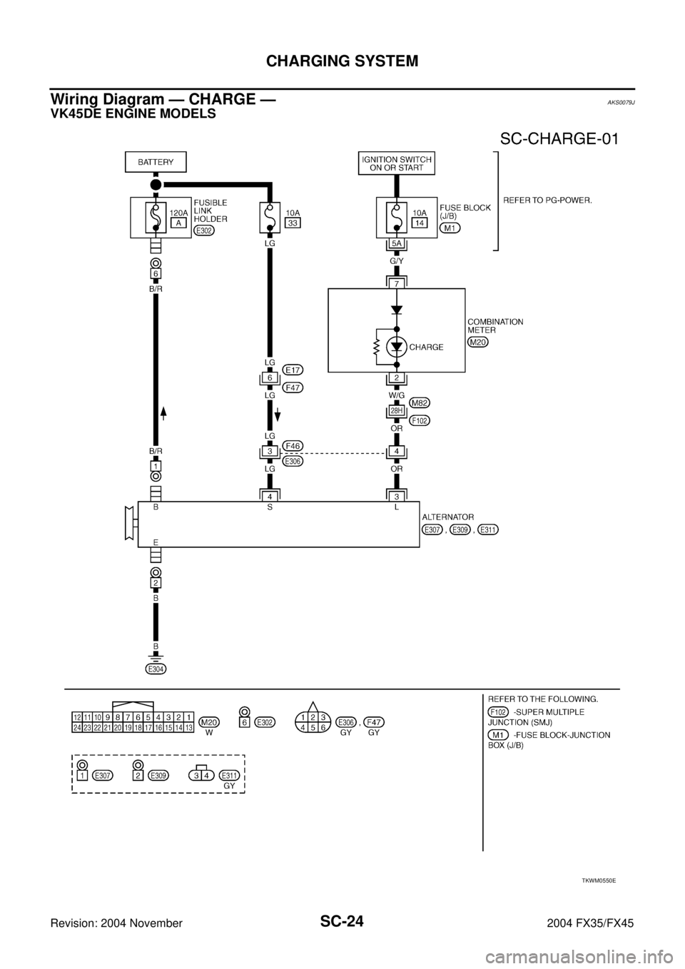
Wiring Diagram — CHARGE —AKS0079J
VK45DE ENGINE MODELS
TKWM0550E
Page 4130 of 4449
SE-1
SEAT
I BODY
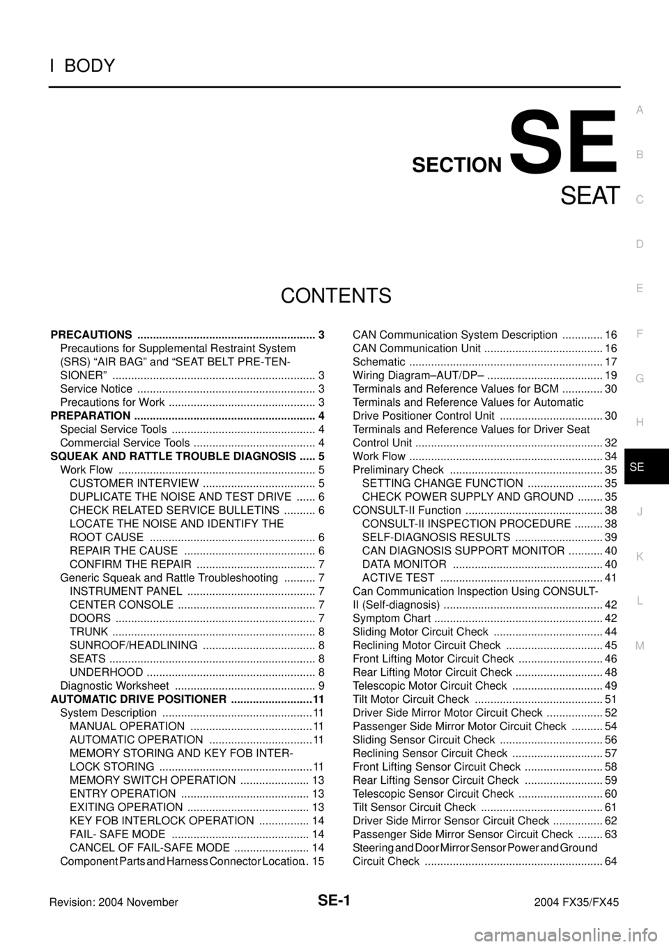
CONTENTS
C
D
E
F
G
H
J
K
L
M
SECTION SE
A
B
SE
Revision: 2004 November 2004 FX35/FX45
SEAT
PRECAUTIONS .......................................................... 3
Precautions for Supplemental Restraint System
(SRS) “AIR BAG” and “SEAT BELT PRE-TEN-
SIONER” .................................................................. 3
Service Notice .......................................................... 3
Precautions for Work ................................................ 3
PREPARATION ........................................................... 4
Special Service Tools ............................................... 4
Commercial Service Tools ........................................ 4
SQUEAK AND RATTLE TROUBLE DIAGNOSIS ...... 5
Work Flow ................................................................ 5
CUSTOMER INTERVIEW ..................................... 5
DUPLICATE THE NOISE AND TEST DRIVE ....... 6
CHECK RELATED SERVICE BULLETINS ........... 6
LOCATE THE NOISE AND IDENTIFY THE
ROOT CAUSE ...................................................... 6
REPAIR THE CAUSE ........................................... 6
CONFIRM THE REPAIR ....................................... 7
Generic Squeak and Rattle Troubleshooting ........... 7
INSTRUMENT PANEL .......................................... 7
CENTER CONSOLE ............................................. 7
DOORS ................................................................. 7
TRUNK .................................................................. 8
SUNROOF/HEADLINING ..................................... 8
SEATS ................................................................... 8
UNDERHOOD ....................................................... 8
Diagnostic Worksheet .............................................. 9
AUTOMATIC DRIVE POSITIONER ...........................11
System Description ................................................. 11
MANUAL OPERATION ........................................ 11
AUTOMATIC OPERATION .................................. 11
MEMORY STORING AND KEY FOB INTER-
LOCK STORING .................................................. 11
MEMORY SWITCH OPERATION ....................... 13
ENTRY OPERATION .......................................... 13
EXITING OPERATION ........................................ 13
KEY FOB INTERLOCK OPERATION ................. 14
FAIL- SAFE MODE ............................................. 14
CANCEL OF FAIL-SAFE MODE ......................... 14
Component Parts and Harness Connector Location ... 15CAN Communication System Description .............. 16
CAN Communication Unit ....................................... 16
Schematic ............................................................... 17
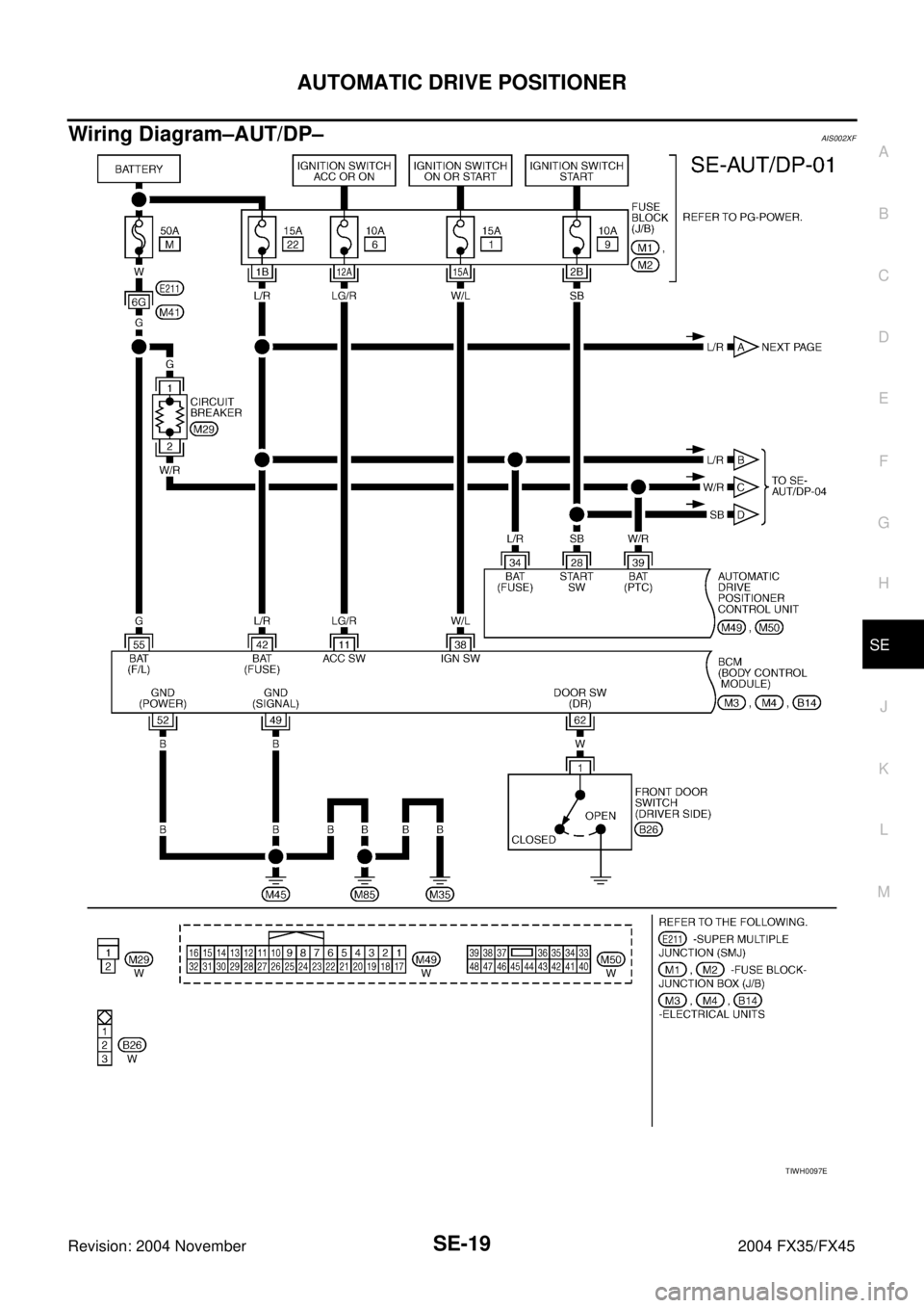
Wiring Diagram–AUT/DP– ...................................... 19
Terminals and Reference Values for BCM .............. 30
Terminals and Reference Values for Automatic
Drive Positioner Control Unit .................................. 30
Terminals and Reference Values for Driver Seat
Control Unit ............................................................. 32
Work Flow ............................................................... 34
Preliminary Check .................................................. 35
SETTING CHANGE FUNCTION ......................... 35
CHECK POWER SUPPLY AND GROUND ......... 35
CONSULT-II Function ............................................. 38
CONSULT-II INSPECTION PROCEDURE .......... 38
SELF-DIAGNOSIS RESULTS ............................. 39
CAN DIAGNOSIS SUPPORT MONITOR ............ 40
DATA MONITOR ................................................. 40
ACTIVE TEST ..................................................... 41
Can Communication Inspection Using CONSULT-
II (Self-diagnosis) .................................................... 42
Symptom Chart ....................................................... 42
Sliding Motor Circuit Check .................................... 44
Reclining Motor Circuit Check ................................ 45
Front Lifting Motor Circuit Check ............................ 46
Rear Lifting Motor Circuit Check ............................. 48
Telescopic Motor Circuit Check .............................. 49
Tilt Motor Circuit Check .......................................... 51
Driver Side Mirror Motor Circuit Check ................... 52
Passenger Side Mirror Motor Circuit Check ........... 54
Sliding Sensor Circuit Check .................................. 56
Reclining Sensor Circuit Check .............................. 57
Front Lifting Sensor Circuit Check .......................... 58
Rear Lifting Sensor Circuit Check .......................... 59
Telescopic Sensor Circuit Check ............................ 60
Tilt Sensor Circuit Check ........................................ 61
Driver Side Mirror Sensor Circuit Check ................. 62
Passenger Side Mirror Sensor Circuit Check ......... 63
Steering and Door Mirror Sensor Power and Ground
Circuit Check .......................................................... 64
Page 4131 of 4449

SE-2Revision: 2004 November 2004 FX35/FX45Front Door Switch (Driver Side) Circuit Check ....... 65
Sliding Switch Circuit Check ................................... 67
Reclining Switch Check .......................................... 68
Front Lifting Switch Circuit Check ........................... 70
Rear Lifting Switch Circuit Check ........................... 71
Sliding Switch and Reclining Switch Ground Circuit
Check ..................................................................... 72
Front Lifting Switch and Rear Lifting Switch Ground
Circuit Check .......................................................... 73
Telescopic Switch Circuit Check ............................. 74
Tilt Switch Circuit Check ......................................... 76
Door Mirror Remote Control Switch (Changeover
switch) Circuit Check .............................................. 78
Door Mirror Remote Control Switch (Mirror Switch)
Circuit Check .......................................................... 80
Detention Switch (P Range Switch) Circuit Check ... 82
Key Switch and Key Lock Solenoid Circuit Check
(With Intelligent Key) .............................................. 83
Key Switch Circuit Check (Without Intelligent Key) ... 85
Seat Memory Switch Circuit Check ........................ 86
Memory Indicator Lamp Circuit Check .................... 88
Uart Communication Line Circuit Check ................. 89
Lumber Support Circuit Check ............................... 91
POWER SEAT ........................................................... 93
Automatic Drive Positioner Interlocking Power Seat ... 93
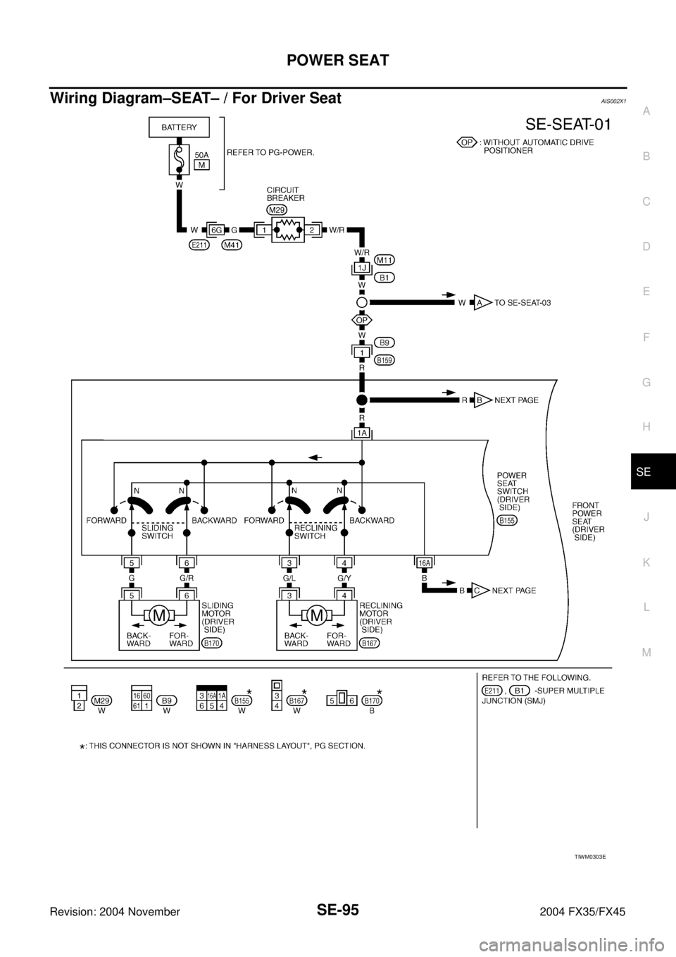
Schematic ............................................................... 94Wiring Diagram–SEAT– / For Driver Seat ............... 95
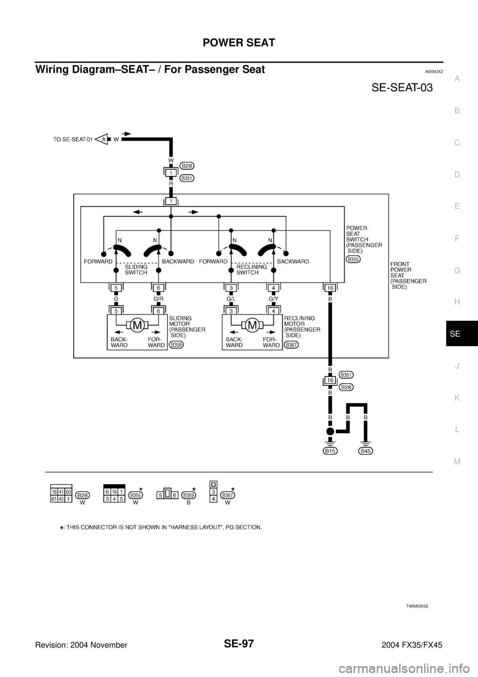
Wiring Diagram–SEAT– / For Passenger Seat ....... 97
HEATED SEAT .......................................................... 98
Description .............................................................. 98
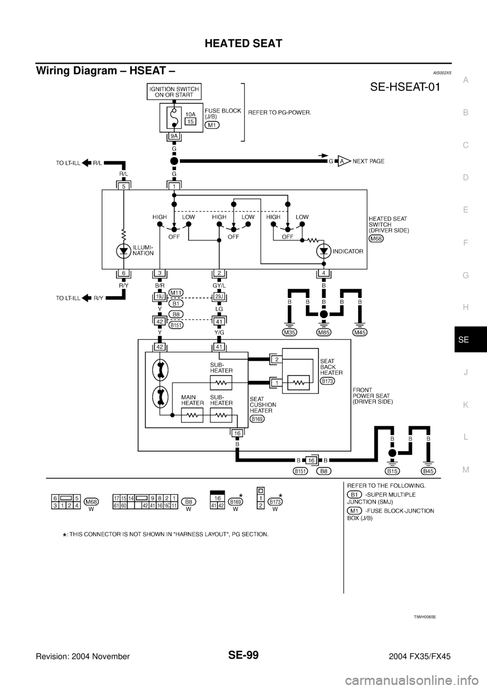
Wiring Diagram – HSEAT – .................................... 99
FRONT SEAT ..........................................................101
Removal and Installation .......................................101
REMOVAL ..........................................................103
INSTALLATION ..................................................104
REMOVAL OF SEATBACK TRIM AND PAD .....104
INSTALLATION OF SEATBACK TRIM AND PAD .105
REMOVAL OF SEAT CUSHION TRIM AND PAD .105
INSTALLATION OF SEAT CUSHION TRIM AND
PAD ....................................................................106
REAR SEAT .............................................................107
Removal and Installation .......................................107
REMOVAL ..........................................................109
INSTALLATION ..................................................109
REMOVAL OF SEAT CUSHION TRIM AND PAD .109
INSTALLATION OF SEAT CUSHION TRIM AND
PAD ....................................................................110
REMOVAL OF SEATBACK TRIM AND PAD .....110
INSTALLATION OF SEATBACK TRIM AND PAD .110
REMOVAL OF REMOTE CONTROL LEVER .... 111
INSTALLATION OF REMOTE CONTROL
LEVER ............................................................... 111
Page 4148 of 4449
AUTOMATIC DRIVE POSITIONER
SE-19
C
D
E
F
G
H
J
K
L
MA
B
SE
Revision: 2004 November 2004 FX35/FX45
Wiring Diagram–AUT/DP–AIS002XF
TIWH0097E
Page 4224 of 4449
POWER SEAT
SE-95
C
D
E
F
G
H
J
K
L
MA
B
SE
Revision: 2004 November 2004 FX35/FX45
Wiring Diagram–SEAT– / For Driver SeatAIS002X1
TIWM0303E
Page 4226 of 4449
POWER SEAT
SE-97
C
D
E
F
G
H
J
K
L
MA
B
SE
Revision: 2004 November 2004 FX35/FX45
Wiring Diagram–SEAT– / For Passenger SeatAIS002X2
TIWM0305E
Page 4228 of 4449
HEATED SEAT
SE-99
C
D
E
F
G
H
J
K
L
MA
B
SE
Revision: 2004 November 2004 FX35/FX45
Wiring Diagram – HSEAT –AIS002X5
TIWH0065E
Page 4242 of 4449
SRS-1
SUPPLEMENTAL RESTRAINT SYSTEM (SRS)
H RESTRAINTS
CONTENTS
C
D
E
F
G
I
J
K
L
M
SECTION SRS
A
B
SRS
Revision: 2004 November 2004 FX35/FX45
SUPPLEMENTAL RESTRAINT SYSTEM (SRS)
PRECAUTIONS .......................................................... 3
Precautions for Supplemental Restraint System
(SRS) “AIR BAG” and “SEAT BELT PRE-TEN-
SIONER” .................................................................. 3
Precautions for SRS “AIR BAG” and “SEAT BELT
PRE-TENSIONER” Service ..................................... 3
Wiring Diagrams and Trouble Diagnosis .................. 3
PREPARATION ........................................................... 4
Special Service Tools ............................................... 4
Commercial Service Tools ........................................ 4
SUPPLEMENTAL RESTRAINT SYSTEM (SRS) ....... 5
SRS Configuration ................................................... 5
Front Seat Belt Pre-tensioner with Load Limiter ...... 6
Front Side Air Bag .................................................... 6
Side Curtain Air Bag ................................................. 6
TROUBLE DIAGNOSIS .............................................. 7
Trouble Diagnosis Introduction ................................. 7
DIAGNOSIS FUNCTION ....................................... 7
HOW TO PERFORM TROUBLE DIAGNOSIS
FOR QUICK AND ACCURATE REPAIR ............... 7
WORK FLOW ........................................................ 8
Component Parts Location ....................................... 9
Schematic .............................................................. 10
Wiring Diagram — SRS — ...................................... 11
CONSULT-II Function ............................................ 15
DIAGNOSIS MODE FOR CONSULT-II ............... 15
HOW TO CHANGE SELF-DIAGNOSIS MODE
WITH CONSULT-II .............................................. 15
HOW TO ERASE SELF-DIAGNOSTIC
RESULTS ............................................................ 16
Self-Diagnosis Function (Without CONSULT-II) ..... 16
HOW TO CHANGE SELF-DIAGNOSIS MODE
WITHOUT CONSULT-II ...................................... 16
HOW TO ERASE SELF-DIAGNOSIS RESULTS ... 16
SRS Operation Check ............................................ 17
DIAGNOSTIC PROCEDURE 1 ........................... 17
Trouble Diagnosis with CONSULT-II ...................... 19
DIAGNOSTIC PROCEDURE 2 ........................... 19
DIAGNOSTIC PROCEDURE 3 ........................... 23
DIAGNOSTIC PROCEDURE 4 (CONTINUED FROM DIAGNOSTIC PROCEDURE 2) .............. 25
DIAGNOSTIC PROCEDURE 5 ........................... 25
Trouble Diagnosis without CONSULT-II ................. 29
DIAGNOSTIC PROCEDURE 6 ........................... 29
WARNING LAMP FLASH CODE CHART ........... 30
Trouble Diagnosis: “AIR BAG” Warning Lamp Does
Not Turn OFF ......................................................... 34
DIAGNOSTIC PROCEDURE 7 ........................... 34
Trouble Diagnosis: “AIR BAG” Warning Lamp Does
Not Turn ON ........................................................... 35
DIAGNOSTIC PROCEDURE 8 ........................... 35
DRIVER AIR BAG MODULE .................................... 36
Removal and Installation ........................................ 36
REMOVAL ........................................................... 36
INSTALLATION ................................................... 37
SPIRAL CABLE ........................................................ 38
Removal and Installation ........................................ 38
REMOVAL ........................................................... 38
INSTALLATION ................................................... 39
FRONT PASSENGER AIR BAG MODULE .............. 40
Removal and Installation ........................................ 40
REMOVAL ........................................................... 40
INSTALLATION ................................................... 40
FRONT SIDE AIR BAG MODULE ............................ 41
Removal and Installation ........................................ 41
REMOVAL ........................................................... 41
INSTALLATION ................................................... 42
SIDE CURTAIN AIR BAG MODULE ........................ 43
Removal and Installation ........................................ 43
REMOVAL ........................................................... 43
INSTALLATION ................................................... 44
CRASH ZONE SENSOR ........................................... 45
Removal and Installation ........................................ 45
REMOVAL ........................................................... 45
INSTALLATION ................................................... 45
SIDE AIR BAG (SATELLITE) SENSOR ................... 46
Removal and Installation ........................................ 46
REMOVAL ........................................................... 46
INSTALLATION ................................................... 46