Page 3628 of 4449
HEADLAMP AIMING CONTROL
LT-73
C
D
E
F
G
H
I
J
L
MA
B
LT
Revision: 2004 November 2004 FX35/FX45
Wiring Diagram — H/AIM —AKS007CF
TKWM0818E
Page 3634 of 4449
FRONT FOG LAMP
LT-79
C
D
E
F
G
H
I
J
L
MA
B
LT
Revision: 2004 November 2004 FX35/FX45
Wiring Diagram — F/FOG —AKS007CL
TKWM0819E
Page 3638 of 4449

FRONT FOG LAMP
LT-83
C
D
E
F
G
H
I
J
L
MA
B
LT
Revision: 2004 November 2004 FX35/FX45
Refer to LT-79, "Wiring Diagram — F/FOG —" .
OK or NG
OK >> GO TO 2.
NG >> If fuse is blown, be sure to eliminate cause of malfunction before installing new fuse. Refer to PG-
3, "POWER SUPPLY ROUTING CIRCUIT" .
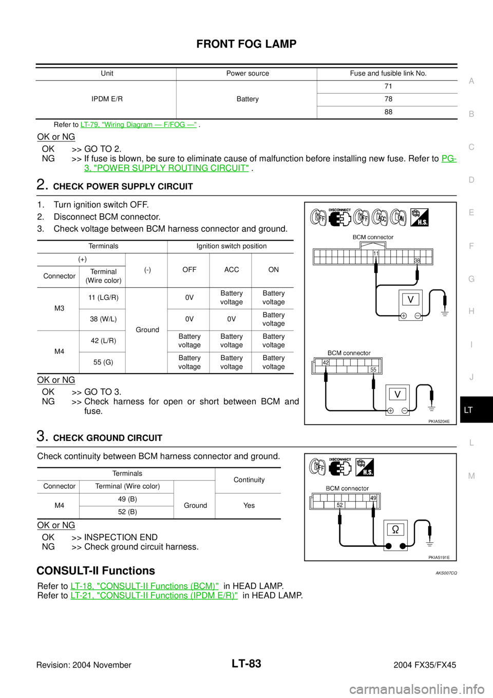
2. CHECK POWER SUPPLY CIRCUIT
1. Turn ignition switch OFF.
2. Disconnect BCM connector.
3. Check voltage between BCM harness connector and ground.
OK or NG
OK >> GO TO 3.
NG >> Check harness for open or short between BCM and
fuse.
3. CHECK GROUND CIRCUIT
Check continuity between BCM harness connector and ground.
OK or NG
OK >> INSPECTION END
NG >> Check ground circuit harness.
CONSULT-II FunctionsAKS007CQ
Refer to LT- 1 8 , "CONSULT-II Functions (BCM)" in HEAD LAMP.
Refer to LT- 2 1 , "
CONSULT-II Functions (IPDM E/R)" in HEAD LAMP.
IPDM E/R Battery71
78
88 Unit Power source Fuse and fusible link No.
Terminals Ignition switch position
(+)
(-) OFF ACC ON
ConnectorTerminal
(Wire color)
M311 (LG/R)
Ground0VBattery
voltageBattery
voltage
38 (W/L) 0V 0VBattery
voltage
M442 (L/R)Battery
voltageBattery
voltageBattery
voltage
55 (G)Battery
voltageBattery
voltageBattery
voltage
PKIA5204E
Terminals
Continuity
Connector Terminal (Wire color)
M449 (B)
Ground Yes
52 (B)
PKIA5191E
Page 3649 of 4449
LT-94
TURN SIGNAL AND HAZARD WARNING LAMPS
Revision: 2004 November 2004 FX35/FX45
Wiring Diagram — TURN —AKS007D0
TKWM0820E
Page 3654 of 4449

TURN SIGNAL AND HAZARD WARNING LAMPS
LT-99
C
D
E
F
G
H
I
J
L
MA
B
LT
Revision: 2004 November 2004 FX35/FX45
Preliminary CheckAKS007D3
CHECK POWER SUPPLY AND GROUND CIRCUIT
1. CHECK FUSES
�Check fuses for blown-out.
Refer to LT-94, "Wiring Diagram — TURN —" .
OK or NG
OK >> GO TO 2.
NG >> If fuse is blown, be sure to eliminate cause of malfunction before installing new fuse. Refer to PG-
3, "POWER SUPPLY ROUTING CIRCUIT" .
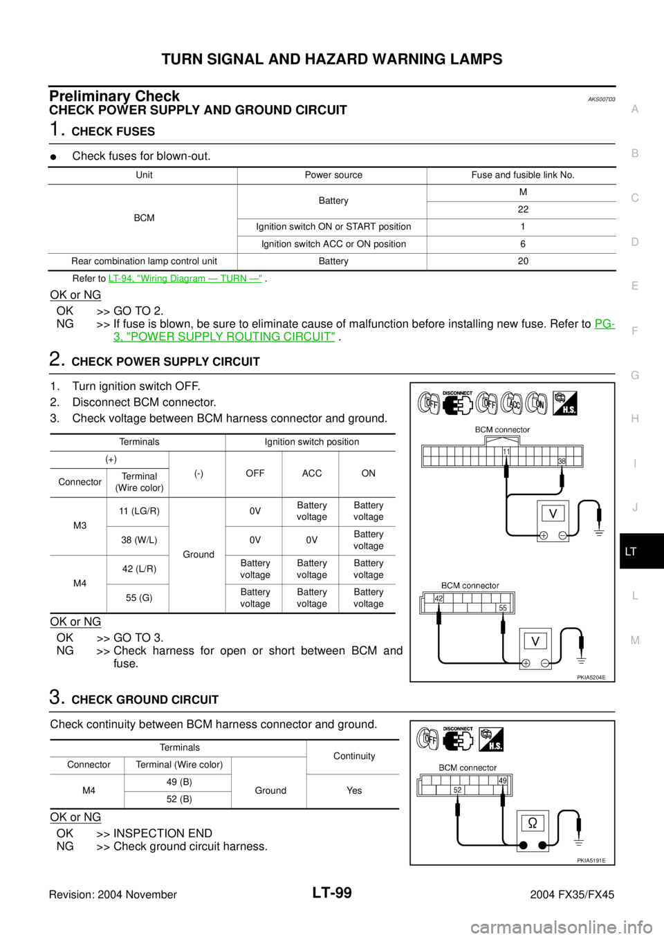
2. CHECK POWER SUPPLY CIRCUIT
1. Turn ignition switch OFF.
2. Disconnect BCM connector.
3. Check voltage between BCM harness connector and ground.
OK or NG
OK >> GO TO 3.
NG >> Check harness for open or short between BCM and
fuse.
3. CHECK GROUND CIRCUIT
Check continuity between BCM harness connector and ground.
OK or NG
OK >> INSPECTION END
NG >> Check ground circuit harness.
Unit Power source Fuse and fusible link No.
BCMBatteryM
22
Ignition switch ON or START position 1
Ignition switch ACC or ON position 6
Rear combination lamp control unit Battery 20
Terminals Ignition switch position
(+)
(-) OFF ACC ON
ConnectorTerminal
(Wire color)
M311 (LG/R)
Ground0VBattery
voltageBattery
voltage
38 (W/L) 0V 0VBattery
voltage
M442 (L/R)Battery
voltageBattery
voltageBattery
voltage
55 (G)Battery
voltageBattery
voltageBattery
voltage
PKIA5204E
Terminals
Continuity
Connector Terminal (Wire color)
M449 (B)
Ground Yes
52 (B)
PKIA5191E
Page 3665 of 4449
LT-110
COMBINATION SWITCH
Revision: 2004 November 2004 FX35/FX45
COMBINATION SWITCHPFP:25567
Wiring Diagram — COMBSW —AKS007G4
TKWM0814E
Page 3673 of 4449
LT-118
STOP LAMP
Revision: 2004 November 2004 FX35/FX45
Wiring Diagram — STOP/L —AKS007DL
TKWH0226E
Page 3680 of 4449
BACK-UP LAMP
LT-125
C
D
E
F
G
H
I
J
L
MA
B
LT
Revision: 2004 November 2004 FX35/FX45
BACK-UP LAMPPFP:26550
Wiring Diagram — BACK/L —AKS007DQ
TKWM1277E