Page 3148 of 4449
TOW TRUCK TOWING
GI-45
C
D
E
F
G
H
I
J
K
L
MB
GI
Revision: 2004 November 2004 FX35/FX45
TOW TRUCK TOWINGPFP:00000
Tow Truck TowingAAS000EH
CAUTION:
�All applicable state or Provincial (in Canada) laws and local laws regarding the towing operation
must be obeyed.
�It is necessary to use proper towing equipment to avoid possible damage to the vehicle during
towing operation. Towing is in accordance with Towing Procedure Manual at dealer.
�Always attach safety chains before towing.
�When towing, make sure that the transmission, steering system and power train are in good order.
If any unit is damaged, dollies must be used.
�Never tow an automatic transmission model from the rear (that is backward) with four wheels on
the ground. This may cause serious and expensive damage to the transmission.
2WD MODELS
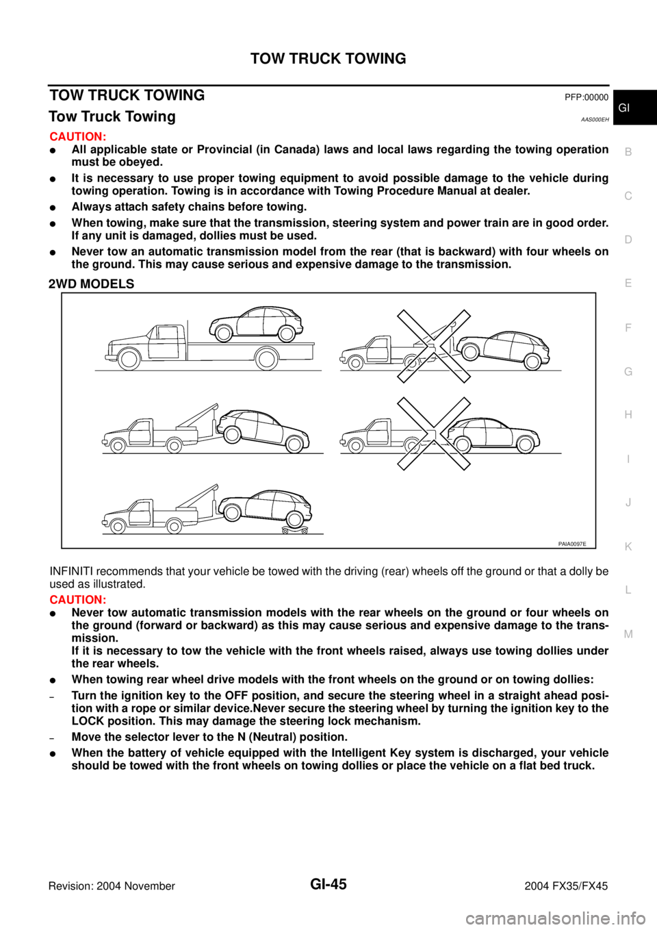
INFINITI recommends that your vehicle be towed with the driving (rear) wheels off the ground or that a dolly be
used as illustrated.
CAUTION:
�Never tow automatic transmission models with the rear wheels on the ground or four wheels on
the ground (forward or backward) as this may cause serious and expensive damage to the trans-
mission.
If it is necessary to tow the vehicle with the front wheels raised, always use towing dollies under
the rear wheels.
�When towing rear wheel drive models with the front wheels on the ground or on towing dollies:
–Turn the ignition key to the OFF position, and secure the steering wheel in a straight ahead posi-
tion with a rope or similar device.Never secure the steering wheel by turning the ignition key to the
LOCK position. This may damage the steering lock mechanism.
–Move the selector lever to the N (Neutral) position.
�When the battery of vehicle equipped with the Intelligent Key system is discharged, your vehicle
should be towed with the front wheels on towing dollies or place the vehicle on a flat bed truck.
PAIA0097E
Page 3187 of 4449
GW-28
POWER WINDOW SYSTEM
Revision: 2004 November 2004 FX35/FX45
Terminal and Reference Value for BCM / With Front Power Window Anti-pinch
System
AIS004Q2
Terminal Wire color Item ConditionVoltage [V]
(Approx.)
12 P/BFront door switch
passenger side signalON (Open) 0
OFF (Close) Battery voltage
22 OR Power window serial link IGN SW ON or power window
timer operating.
38 W/L Ignition switch (ON or START) Ignition switch
(ON or START position)Battery voltage
39 L CAN - H — —
40 R CAN - L — —
42 L/R Battery power supply — Battery voltage
49 B Ground (signal) — 0
52 B Ground (power) — 0
53 Y/B Rap signalIGN SW ON Battery voltage
Within 45 second after ignition
switch is turned to OFFBattery voltage
When driver side or passenger
side door is open in power win-
dow timer is operates0
54 W Power window power supply — Battery voltage
55 G Battery power supply — Battery voltage
62 WFront door switch
driver side signalON (Open) 0
OFF (Close) Battery voltage
PIIA2344J
Page 3188 of 4449
POWER WINDOW SYSTEM
GW-29
C
D
E
F
G
H
J
K
L
MA
B
GW
Revision: 2004 November 2004 FX35/FX45
Terminal and Reference Value for Power Window Main Switch / With Front
Power Window Anti-pinch System
AIS004Q3
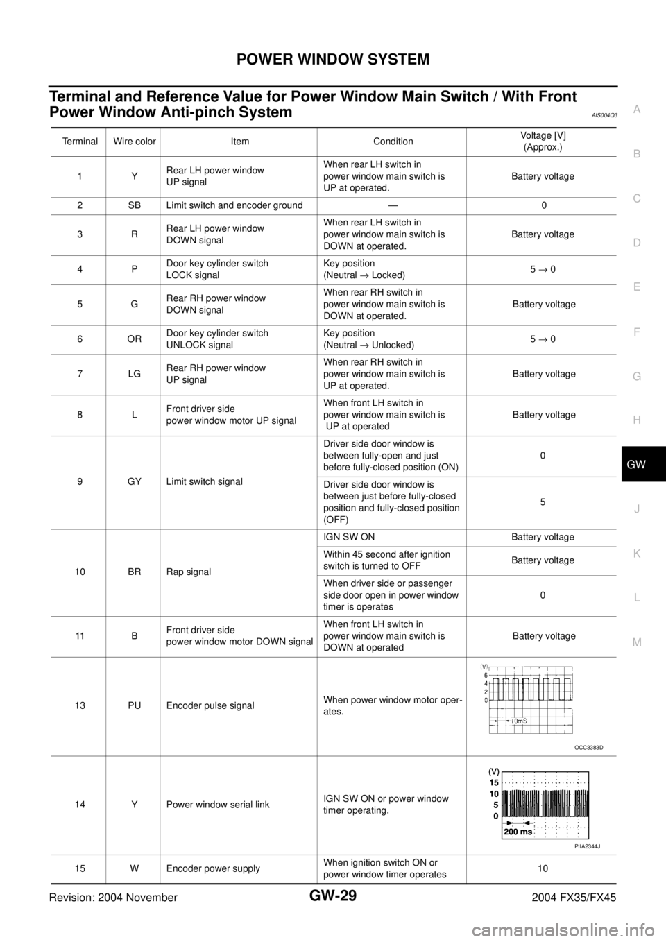
Terminal Wire color Item ConditionVoltage [V]
(Approx.)
1YRear LH power window
UP signalWhen rear LH switch in
power window main switch is
UP at operated.Battery voltage
2 SB Limit switch and encoder ground — 0
3RRear LH power window
DOWN signalWhen rear LH switch in
power window main switch is
DOWN at operated.Battery voltage
4PDoor key cylinder switch
LOCK signalKey position
(Neutral → Locked)5 → 0
5GRear RH power window
DOWN signalWhen rear RH switch in
power window main switch is
DOWN at operated. Battery voltage
6ORDoor key cylinder switch
UNLOCK signalKey position
(Neutral → Unlocked)5 → 0
7LGRear RH power window
UP signalWhen rear RH switch in
power window main switch is
UP at operated. Battery voltage
8LFront driver side
power window motor UP signalWhen front LH switch in
power window main switch is
UP at operated Battery voltage
9 GY Limit switch signalDriver side door window is
between fully-open and just
before fully-closed position (ON)0
Driver side door window is
between just before fully-closed
position and fully-closed position
(OFF)5
10 BR Rap signalIGN SW ON Battery voltage
Within 45 second after ignition
switch is turned to OFFBattery voltage
When driver side or passenger
side door open in power window
timer is operates0
11 BFront driver side
power window motor DOWN signalWhen front LH switch in
power window main switch is
DOWN at operated Battery voltage
13 PU Encoder pulse signalWhen power window motor oper-
ates.
14 Y Power window serial linkIGN SW ON or power window
timer operating.
15 W Encoder power supplyWhen ignition switch ON or
power window timer operates10
OCC3383D
PIIA2344J
Page 3189 of 4449
GW-30
POWER WINDOW SYSTEM
Revision: 2004 November 2004 FX35/FX45
Terminal and Reference Value for Front Power Window Switch (Passenger Side)
/ With Front Power Window Anti-pinch System
AIS004Q4
17 B Ground — 0
19 W Battery power supply — Battery voltage Terminal Wire color Item ConditionVoltage [V]
(Approx.)
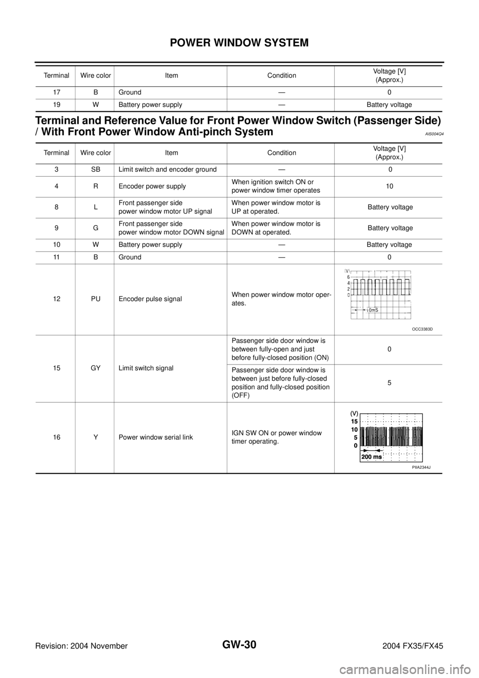
Terminal Wire color Item ConditionVoltage [V]
(Approx.)
3 SB Limit switch and encoder ground — 0
4 R Encoder power supplyWhen ignition switch ON or
power window timer operates10
8LFront passenger side
power window motor UP signalWhen power window motor is
UP at operated. Battery voltage
9GFront passenger side
power window motor DOWN signalWhen power window motor is
DOWN at operated. Battery voltage
10 W Battery power supply — Battery voltage
11 B Ground — 0
12 PU Encoder pulse signalWhen power window motor oper-
ates.
15 GY Limit switch signalPassenger side door window is
between fully-open and just
before fully-closed position (ON)0
Passenger side door window is
between just before fully-closed
position and fully-closed position
(OFF)5
16 Y Power window serial linkIGN SW ON or power window
timer operating.
OCC3383D
PIIA2344J
Page 3196 of 4449
POWER WINDOW SYSTEM
GW-37
C
D
E
F
G
H
J
K
L
MA
B
GW
Revision: 2004 November 2004 FX35/FX45
Terminal and Reference Value for BCM / With Front and Rear Power Window
Anti-pinch
AIS004Q7
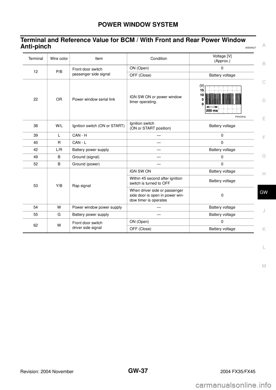
Terminal Wire color Item ConditionVoltage [V]
(Approx.)
12 P/BFront door switch
passenger side signalON (Open) 0
OFF (Close) Battery voltage
22 OR Power window serial linkIGN SW ON or power window
timer operating.
38 W/L Ignition switch (ON or START) Ignition switch
(ON or START position)Battery voltage
39 L CAN - H — 0
40 R CAN - L — 0
42 L/R Battery power supply — Battery voltage
49 B Ground (signal) — 0
52 B Ground (power) — 0
53 Y/B Rap signalIGN SW ON Battery voltage
Within 45 second after ignition
switch is turned to OFFBattery voltage
When driver side or passenger
side door is open in power win-
dow timer is operates0
54 W Power window power supply — Battery voltage
55 G Battery power supply — Battery voltage
62 WFront door switch
driver side signalON (Open) 0
OFF (Close) Battery voltage
PIIA2344J
Page 3197 of 4449
GW-38
POWER WINDOW SYSTEM
Revision: 2004 November 2004 FX35/FX45
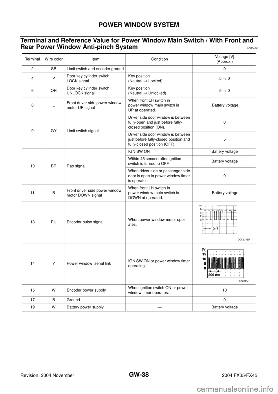
Terminal and Reference Value for Power Window Main Switch / With Front and
Rear Power Window Anti-pinch System
AIS004Q8
Terminal Wire color Item ConditionVoltage [V]
(Approx.)
2 SB Limit switch and encoder ground — 0
4PDoor key cylinder switch
LOCK signalKey position
(Neutral → Locked)5 → 0
6ORDoor key cylinder switch
UNLOCK signalKey position
(Neutral → Unlocked)5 → 0
8LFront driver side power window
motor UP signalWhen front LH switch in
power window main switch is
UP at operated. Battery voltage
9 GY Limit switch signalDriver side door window is between
fully-open and just before fully-
closed position (ON).0
Driver side door window is between
just before fully-closed position and
fully-closed position (OFF).5
10 BR Rap signalIGN SW ON Battery voltage
Within 45 second after ignition
switch is turned to OFFBattery voltage
When driver side or passenger side
door is open in power window timer
is operates0
11 BFront driver side power window
motor DOWN signalWhen front LH switch in
power window main switch is
DOWN at operated. Battery voltage
13 PU Encoder pulse signalWhen power window motor oper-
ates.
14 Y Power window serial linkIGN SW ON or power window timer
operating.
15 W Encoder power supplyWhen ignition switch ON or power
window timer operates.10
17 B Ground — 0
19 W Battery power supply — Battery voltage
OCC3383D
PIIA2344J
Page 3198 of 4449
POWER WINDOW SYSTEM
GW-39
C
D
E
F
G
H
J
K
L
MA
B
GW
Revision: 2004 November 2004 FX35/FX45
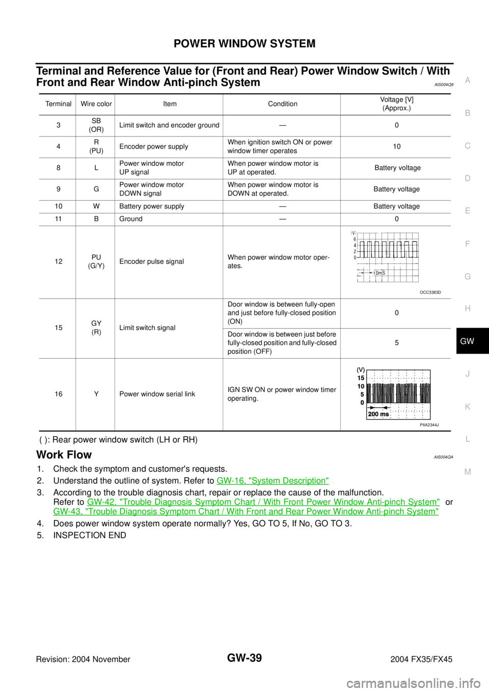
Terminal and Reference Value for (Front and Rear) Power Window Switch / With
Front and Rear Window Anti-pinch System
AIS004Q9
( ): Rear power window switch (LH or RH)
Work FlowAIS004QA
1. Check the symptom and customer's requests.
2. Understand the outline of system. Refer to GW-16, "
System Description"
3. According to the trouble diagnosis chart, repair or replace the cause of the malfunction.
Refer to GW-42, "
Trouble Diagnosis Symptom Chart / With Front Power Window Anti-pinch System" or
GW-43, "
Trouble Diagnosis Symptom Chart / With Front and Rear Power Window Anti-pinch System"
4. Does power window system operate normally? Yes, GO TO 5, If No, GO TO 3.
5. INSPECTION END
Terminal Wire color Item ConditionVoltage [V]
(Approx.)
3SB
(OR)Limit switch and encoder ground — 0
4R
(PU)Encoder power supplyWhen ignition switch ON or power
window timer operates10
8LPower window motor
UP signalWhen power window motor is
UP at operated. Battery voltage
9GPower window motor
DOWN signalWhen power window motor is
DOWN at operated.Battery voltage
10 W Battery power supply — Battery voltage
11 B G r o u n d — 0
12PU
(G/Y)Encoder pulse signalWhen power window motor oper-
ates.
15GY
(R)Limit switch signalDoor window is between fully-open
and just before fully-closed position
(ON)0
Door window is between just before
fully-closed position and fully-closed
position (OFF)5
16 Y Power window serial linkIGN SW ON or power window timer
operating.
OCC3383D
PIIA2344J
Page 3203 of 4449
![INFINITI FX35 2004 Service Manual GW-44
POWER WINDOW SYSTEM
Revision: 2004 November 2004 FX35/FX45
BCM Power Supply and Ground Circuit CheckAIS004QE
1. CHECK FUSE
�Check 15A fuse [No.1, located in fuse block (J/B)]
�Check 15A fuse [No INFINITI FX35 2004 Service Manual GW-44
POWER WINDOW SYSTEM
Revision: 2004 November 2004 FX35/FX45
BCM Power Supply and Ground Circuit CheckAIS004QE
1. CHECK FUSE
�Check 15A fuse [No.1, located in fuse block (J/B)]
�Check 15A fuse [No](/manual-img/42/57021/w960_57021-3202.png)
GW-44
POWER WINDOW SYSTEM
Revision: 2004 November 2004 FX35/FX45
BCM Power Supply and Ground Circuit CheckAIS004QE
1. CHECK FUSE
�Check 15A fuse [No.1, located in fuse block (J/B)]
�Check 15A fuse [No.22, located in fuse block (J/B)]
�Check 50A fusible link (letter M located in the fuse and fusible link box).
NOTE:
Refer to GW-15, "
Component Parts and Harness Connector Location" .
OK or NG
OK >> GO TO 2.
NG >> If fuse is blown out, be sure to eliminate cause of malfunction before installing new fuse. Refer to
PG-3, "
POWER SUPPLY ROUTING CIRCUIT" .
2. CHECK POWER SUPPLY CIRCUIT
1. Turn ignition switch ON.
2. Check voltage between BCM connector M3, M4 terminal 38, 42,
55 and ground.
OK or NG
OK >> GO TO 3.
NG >> Check BCM power supply circuit for open or short.
Power window retained power operation does not operate
properly1. Check the retained power operation mode set-
ting.GW-41
2. Door switch checkGW-67
3. Replace BCM.BCS-15
Does not operate by key cylinder switch1. Door key cylinder switch checkGW-692. Replace power window main switch —
Power window lock switch does not function 1. Power window lock switch checkGW-73
Auto operation does not operate but manual operate normally
(driver side)1. Encoder circuit check (driver side)GW-61
2. Replace power window main switch —
Auto operation does not operate but manual operate normally
(passenger side)1. Encoder circuit check (passenger side)GW-63
2. Replace front power window switch (passen-
ger side)—
Auto operation does not operate but manual operate normally
(rear LH or RH)1. Encoder circuit check (rear LH or RH)GW-65
2. Replace rear power window switch (LH or RH) — Symptom Repair order Refer to page
38 (W/L) – Ground : Battery voltage
42 (L/R) – Ground : Battery voltage
55 (G) – Ground : Battery voltage
PIIA6160E