Page 3947 of 4449

PS-14
STEERING COLUMN
Revision: 2004 November 2004 FX35/FX45
INSPECTION AFTER REMOVAL
�Check if there is something wrong with jacket tube of steering column assembly and collar etc. And then if
they are damaged, replace with new one.
�If vehicle has a collision light shocked, check column length “L”
as shown in the figure. Then if it is out of the specified value,
replace with new one.
�Check the turning torque of steering column with preload gauge
(SST). If it is out of the specified value, repair it or replace with
new one.
INSTALLATION
�Refer to PS-12, "Removal and Installation" for tightening torque. Install in the reverse order of removal.
NOTE:
Refer to component parts location and do not reuse non-reusable parts.
�After removing/installing or replacing steering components, check wheel alignment. Refer to FSU-6,
"Wheel Alignment Inspection" .
�After adjusting wheel alignment, adjust neutral position of steering angle sensor. Refer to BRC-6, "Adjust-
ment of Steering Angle Sensor Neutral Position" .
INSPECTION AFTER INSTALLATION
�After installing steering column to vehicle, check tilt device and
its operation range. Ranges of operation are shown in the figure.
�Check if steering wheel operation can turn to the end of the left
and right smoothly.Steering column length “L”: 572 mm (22.52 in)
Turning torque : 0 − 0.2 N·m (0 − 0.021 kg-m, 0 − 1 in-lb)
SGIA0556E
SGIA0558E
Page 3953 of 4449

from steering gear assembly, then drain fluid from pipings")
PS-20
POWER STEERING GEAR AND LINKAGE
Revision: 2004 November 2004 FX35/FX45
7. Remove oil pipings (high pressure side and low pressure side)
from steering gear assembly, then drain fluid from pipings.
8. Remove mounting bolt of steering hydraulic piping bracket from
steering gear assembly.
9. Remove mounting bolt (lower side) of lower joint.
10. Remove mounting bolts of steering gear assembly with power
tool, and then remove steering gear assembly from vehicle.
INSTALLATION
�Refer to PS-19, "Removal and Installation" for tightening torque. Install in the reverse order of removal.
NOTE:
Refer to component parts location and do not reuse non-reusable parts.
�After removing/installing or replacing steering components, check wheel alignment. Refer to FSU-6,
"Wheel Alignment Inspection" .
�After adjusting wheel alignment, adjust neutral position of steering angle sensor. Refer to BRC-6, "Adjust-
ment of Steering Angle Sensor Neutral Position" .
SGIA0541E
SGIA0545E
SGIA0542E
SGIA0546E
Page 3979 of 4449

Revision: 2004 November 2004 FX35/FX45
SERVICE DATA AND SPECIFICATIONS (SDS)PFP:00030
Steering WheelAGS000H7
Steering AngleAGS000H8
Steering ColumnAGS000H9")
PS-46
SERVICE DATA AND SPECIFICATIONS (SDS)
Revision: 2004 November 2004 FX35/FX45
SERVICE DATA AND SPECIFICATIONS (SDS)PFP:00030
Steering WheelAGS000H7
Steering AngleAGS000H8
Steering ColumnAGS000H9
Steering Outer Socket and Inner SocketAGS000HA
End play of the axle direction for steering wheel 0 mm (0 in)
Steering wheel play on the outer circumference 0 − 35 mm (0 − 1.38 in)
Inner wheel
Degree minute (Decimal degree)Minimum 32°00′ (32.0°)
Nominal 35°00′ (35.0°)
Maximum 36°00′ (36.0°)
Outer wheel
Degree minute (Decimal degree)Nominal 30°00′ (30.0°)
Steering column length “ L1 ” 572 mm (22.52 in)
SGIA0556E
Steering gear typePR26AM
Tie-rod ball joint outer socketSwinging torque 0.3 − 2.9 N·m (0.03 − 0.29 kg-m, 3 − 25 in-lb)
Measurement on spring balance
�Measuring point: cotter pin hole of stud4.84 − 46.7 N (0.50 − 4.7 kg, 4 − 34 lb)
Rotating torque 0.3 − 2.9 N·m (0.03 − 0.29 kg-m, 3 − 25 in-lb)
Axial end play 0.5 mm (0.020 in) or less
Tie-rod ball joint inner socketSwinging torque 1.0 − 7.8 N·m (0.11 − 0.79 kg-m, 9 − 69 in-lb)
Measurement on spring balance
�Measuring point: L mark see below,
L=83.2 mm (3.276 in).12.1 − 93.7 N (1.3 − 9.5 kg, 9 − 69 lb)
Axial end play 0.2 mm (0.08 in) or less
SGIA0358E
Page 3984 of 4449
ADS000C1
The actual shapes of Kent-Moore tools may differ from those")
PREPARATION
RAX-3
C
E
F
G
H
I
J
K
L
MA
B
RAX
Revision: 2004 November 2004 FX35/FX45
PREPARATIONPFP:00002
Special Service Tools (SST)ADS000C1
The actual shapes of Kent-Moore tools may differ from those of special service tools illustrated here.
Commercial Service ToolsADS000C2
Tool number
(Kent-Moore No.)
Tool nameDescription
ST33251000
( — )
Drift
�Removing wheel hub
�Removing wheel bearing outer side
inner race
�Installing wheel hub
�Inspection of wheel bearing rotating
torque
ST35300000
( — )
Drift
a: 45 mm (1.77 in) dia.
b: 59 mm (2.32 in) dia.
�Installing wheel hub
�Inspection of wheel bearing rotating
torque
KV40100900
( — )
Drift
a: 52 mm (2.05 in) dia.
b: —Wheel bearing rotating torque
inspection
KV38100500
( — )
Drift
a: 80 mm (3.15 in) dia.
b: 60 mm (2.36 in) dia.Installing drive shaft plug
KV38102200
( — )
Drift
a: 90 mm (3.54 in) dia.
b: 31 mm (1.22 in) dia.Installing drive shaft plug
ZZA0982D
ZZA0881D
ZZA0539D
ZZA0701D
ZZA0920D
Tool nameDescription
Power tool
�Removing wheel nuts
�Removing brake caliper assembly
�Removing wheel hub and bearing
assembly
�Removing suspension links
�Removing drive shaft fixing bolts
and nutsPBIC0190E
Page 3987 of 4449

RAX-6
WHEEL HUB
Revision: 2004 November 2004 FX35/FX45
10. Loosen fixing bolts and nuts of front lower link, radius rod, and rear lower link in side of suspension mem-
ber.
11. Set jack under rear lower link. Then remove fixing bolt in front lower link side of shock absorber with
power tool.
12. Remove bolt and nut in axle side of rear lower link with power tool. Then remove coil spring. Refer to
RSU-15, "
REAR LOWER LINK & COIL SPRING" .
13. Remove fixing bolts and nuts in axle side of front lower link, radius rod with power tool.
14. Remove suspension arm and cotter pin at axle, then loosen mounting nut.
15. Use a ball joint remover (suitable tool) to remove suspension arm from axle. Be careful not to damage ball
joint boot.
CAUTION:
Tighten temporarily mounting nut to prevent damage to threads and to prevent ball joint remover
(suitable tool) from coming off.
16. Remove axle from vehicle.
INSPECTION AFTER REMOVAL
Ball Joint Inspection
Check for boot breakage, axial looseness, and torque of suspension arm ball joint. Refer to RSU-11,
"INSPECTION AFTER REMOVAL" .
INSTALLATION
�Refer to RAX-5, "Removal and Installation" for tightening torque. Install in the reverse order of removal.
NOTE:
Refer to component parts location and do not reuse non-reusable parts.
�Perform final tightening of installation position of suspension links (rubber bushing) under unladen condi-
tions with tires on level ground, Check wheel alignment. Refer to RSU-5, "
Wheel Alignment Inspection" .
�After adjusting wheel alignment, adjust neutral position of steering angle sensor. Refer to BRC-6, "Adjust-
ment of Steering Angle Sensor Neutral Position" .
Disassembly and AssemblyADS000C6
DISASSEMBLY
Wheel Bearing
CAUTION:
Do not disassemble if wheel bearing has no trouble.
1. Remove wheel bearing fixing bolts and anchor block fixing nuts, and remove wheel hub and bearing
assembly, back plate and anchor block from axle.
2. Using a drift (SST) and a puller (suitable tool), press wheel hub
out to remove from wheel bearing.
SDIA1482E
Page 3989 of 4449
RAX-8
WHEEL HUB
Revision: 2004 November 2004 FX35/FX45
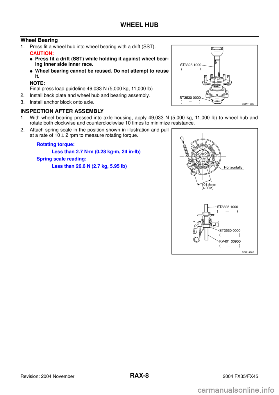
Wheel Bearing
1. Press fit a wheel hub into wheel bearing with a drift (SST).
CAUTION:
�Press fit a drift (SST) while holding it against wheel bear-
ing inner side inner race.
�Wheel bearing cannot be reused. Do not attempt to reuse
it.
NOTE:
Final press load guideline 49,033 N (5,000 kg, 11,000 lb)
2. Install back plate and wheel hub and bearing assembly.
3. Install anchor block onto axle.
INSPECTION AFTER ASSEMBLY
1. With wheel bearing pressed into axle housing, apply 49,033 N (5,000 kg, 11,000 lb) to wheel hub and
rotate both clockwise and counterclockwise 10 times to minimize resistance.
2. Attach spring scale in the position shown in illustration and pull
at a rate of 10 ± 2 rpm to measure rotating torque.
SDIA1120E
Rotating torque:
Less than 2.7 N·m (0.28 kg-m, 24 in-lb)
Spring scale reading:
Less than 26.6 N (2.7 kg, 5.95 lb)
SDIA1486E
Page 3990 of 4449

REAR DRIVE SHAFT
RAX-9
C
E
F
G
H
I
J
K
L
MA
B
RAX
Revision: 2004 November 2004 FX35/FX45
REAR DRIVE SHAFTPFP:39600
Removal and InstallationADS000C7
REMOVAL
1. Remove tire with power tool.
2. Remove cotter pin. Then remove lock nut from drive shaft.
3. Remove fixing nuts and bolts between side flange and drive shaft with power tool.
4. Separate drive shaft from wheel hub and bearing assembly by lightly tapping the end with a suitable ham-
mer and wood block. If it is hard to separate, use a suitable puller.
5. Remove drive shaft from axle.
CAUTION:
When removing drive shaft, do not apply an excessive angle to drive shaft joint. Also be careful
not to excessively extend slide joint.
INSPECTION AFTER REMOVAL
�Move joint up/down, left/right, and in the axial direction. Check
for any rough movement or significant looseness.
�Check boot for cracks or other damage, and also for grease
leakage.
�If a trouble is found, disassemble drive shaft, and then replace
with new one.
INSTALLATION
Refer to RAX-9, "Removal and Installation" for tightening torque. Install in the reverse order of removal.
NOTE:
Refer to component parts location and do not reuse non-reusable parts.
1. Side flange 2. Cotter pin
SDIA1487E
RAA0030D
Page 3996 of 4449
SERVICE DATA
RAX-15
C
E
F
G
H
I
J
K
L
MA
B
RAX
Revision: 2004 November 2004 FX35/FX45
SERVICE DATAPFP:00030
Wheel BearingADS000C9
Drive ShaftADS000KS
Axial end play0 mm (0 in)
Rotational torqueAt a load of 49,033 N (5,000 kg, 11,000 lb)
Less than 2.7 N·m (0.28 kg-m, 24 in-lb)
Measurement of spring scale Less than 26.6 N (2.7 kg, 5.95 lb)
Measuring point (Brake caliper installation points)
SDIA0801E
Joint Wheel side Final drive side
Engine model VQ35DE VK45DE VQ35DE VK45DE
Grease quantity86 − 96 g
(3.03 − 3.39 oz)140 − 160 g
(4.93 − 5.64 oz)124 − 134 g
(4.37 − 4.73 oz)175 − 195 g
(6.17 − 6.88 oz)
Boots installed length 97 mm (3.82 in) 141.5 mm (5.57 in) 93.9 mm (3.697 in) 147.9 mm (5.82 in)

Rotational torqueAt a lo")