Page 954 of 4449

INTELLIGENT KEY SYSTEM
BL-147
C
D
E
F
G
H
J
K
L
MA
B
BL
Revision: 2004 November 2004 FX35/FX45
Intelligent Key InspectionAIS004NU
INTELLIGENT KEY DISASSEMBLY AND ASSEMBLY
1. Remove Intelligent Key cover.
2. Insert a thin screwdriver wrapped with tape into Area A and then
separate lower and upper cases while twisting screwdriver.
3. When replacing the circuit board or rubber
�Remove the circuit board assembly from the upper case.
(Substrate assembly: circuit board + rubber)
�Gently press the rubber and remove the circuit board.
CAUTION:
Be careful not to touch the printed circuits directly.
4. When replacing the battery
�Remove the battery from the lower case and replace it.
CAUTION:
When replacing battery, be sure to keep dirt, grease, and
other foreign materials off the electrode contact area.
5. After replacement, assemble the upper and lower cases by
engaging the hooks on their circumference while being careful
not to pinch the rubber, etc.
CAUTION:
After replacing the battery, check to make sure all Intelli-
gent Key functions work normally.
REMOTE CONTROLLER BATTERY INSPECTION
Check by connecting a resistance (approximately 300Ω) so that the
current value becomes about 10 mA.
PIIA6638E
Battery replace-
ment: Coin-shaped lithium battery 3V (CR2032)
PIIA6639E
Standard : Approx. 2.5V - 3.0V
OCC0607D
Page 972 of 4449

BACK DOOR AUTO CLOSURE SYSTEM
BL-165
C
D
E
F
G
H
J
K
L
MA
B
BL
Revision: 2004 November 2004 FX35/FX45
BACK DOOR AUTO CLOSURE SYSTEMPFP:90542
Component Parts and Harness Connector LocationAIS004OD
System DescriptionAIS004OE
When back door lock latch engaged with striker, striker is lowered by means of a motor the back door fully
closed.
CLOSE OPERATION
�Half-latch is turned off when back door enters the state of a half door and back door closure control unit
recognizes it.
�Back door closure control unit by which the signal is recognized operates closure motor in the close direc-
tion, and open switch is turned on.
�Close switch is turned on when back door becomes a full latch position by operating closure motor and
back door closure control unit operates closure motor in an open direction.
�The operation of closure motor is stopped, and back door enters all close states when back door moves in
an open direction, and open switch is turned off.
NON-OPERATION CONDITION
�When you close back door while pushing back door opener switch.
�When closing at once (within about 0.5 seconds) after back door is opened.
�When you do not close back door after back door opener switch is pushed.
PIIA6406E
Page 973 of 4449
BL-166
BACK DOOR AUTO CLOSURE SYSTEM
Revision: 2004 November 2004 FX35/FX45
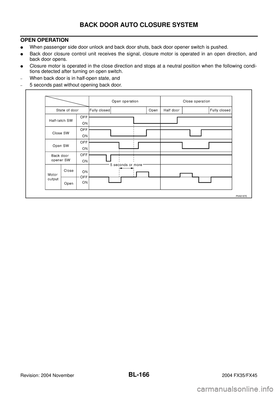
OPEN OPERATION
�When passenger side door unlock and back door shuts, back door opener switch is pushed.
�Back door closure control unit receives the signal, closure motor is operated in an open direction, and
back door opens.
�Closure motor is operated in the close direction and stops at a neutral position when the following condi-
tions detected after turning on open switch.
–When back door is in half-open state, and
–5 seconds past without opening back door.
PIIA6187E
Page 976 of 4449
BACK DOOR AUTO CLOSURE SYSTEM
BL-169
C
D
E
F
G
H
J
K
L
MA
B
BL
Revision: 2004 November 2004 FX35/FX45
Terminals and Reference Value for Back Door Closure Control UnitAIS004OG
*, (): Models with Intelligent KeyTe r m i -
nalWire
colorItem ConditionVoltage (V)
(Approx.)
1 R Battery power supply — Battery voltage
2 PU Closure motor (open) signal Fully close → fully open
3 G Closure motor (close) signal Fully open → fully close
4 B Ground — 0
5W
(B)Ground* — 0*
Unlock sensor signal
(passenger side)Passenger side door lock is locked 5
Passenger side door lock is unlocked 0
6Y
(LG)Back door opener switch signalBack door opener switch is ON 0
Other than above 5
7 OR Half-latch switch signal Fully open → fully close
8 L Close switch signal Fully open → fully close
9 P Open switch signal Fully open → fully close
SIIA1480J
SIIA1480J
SIIA1479J
SIIA1478J
SIIA1481J
Page 977 of 4449

BL-170
BACK DOOR AUTO CLOSURE SYSTEM
Revision: 2004 November 2004 FX35/FX45
Work FlowAIS004OH
1. Check the symptom and customer's requests.
2. Understand the outline of system. Refer to BL-165, "
System Description" .
3. Perform the preliminary check, Refer to BL-170, "
Preliminary Check"
4. According to the trouble diagnosis chart, repair or replace the cause of the malfunction. Refer to BL-170,
"Trouble Diagnosis Chart by Symptom" .
5. Does back door auto closure system operate normally? If Yes, GO TO 6, If No, GO TO 4.
6. INSPECTION END
Preliminary CheckAIS004OI
Remove the fuse No.18 for the back door closure with the back door closure inactive.
Check that the back door can be open / close normally.
CAUTION:
It is judged it is abnormal, discontinues closure operation, and drive lever returns to a neutral position
if not becoming full-latch within about three seconds after half-latch.
When this operation is done continuously three times, both back door closure and back door opener
switch are not operated because the function of back door closure is stopped.
Thing to reset power supply by pulling out and opening fuse in that case.
Trouble Diagnosis Chart by SymptomAIS004OJ
Symptom Diagnostic procedure and repair order Refer to page
Back door closure does not operate.1.Back door closure motor power supply and ground
circuit check BL-171
2. Half-latch switch checkBL-171
3. Close switch checkBL-173
4. Open switch check.BL-174
5. Closure motor check.BL-180
6. Replace back door closure control unit.BL-180
Back door does not open (with Intelligent Key system).1. Intelligent Key system check.BL-1132. Back door opener switch check.BL-175
Back door does not open1. Back door opener switch check.BL-1772. Unlock sensor check.BL-179
3. Replace back door closure control unit.BL-180
Back door does not enter fully closed states through
back door closure operates.1.Back door fitting adjustment.BL-159
2. Replace back door lock assembly.BL-163
Page 978 of 4449

BACK DOOR AUTO CLOSURE SYSTEM
BL-171
C
D
E
F
G
H
J
K
L
MA
B
BL
Revision: 2004 November 2004 FX35/FX45
Back Door Closure Control Unit Power Supply and Ground Circuit CheckAIS004OK
1. CHECK POWER SUPPLY CIRCUIT
1. Turn ignition switch OFF.
2. Check voltage between back door closure control unit connector
D106 terminal 1 and ground.
OK or NG
OK >> GO TO 2.
NG >> Check the following.
�15A fuse [No.18, located in fuse block (J/B)]
�Harness for open or short between back door closure
control unit and fuse.
2. CHECK GROUND CIRCUIT
1. Disconnect back door closure control unit connector.
2. Check continuity between back door closure control unit con-
nector D106 terminal 4 and ground.
OK or NG
OK >> Power supply and ground circuit are OK.
NG >> Repair or replace harness.
Half-Latch Switch CheckAIS004OL
1. CHECK HALF-LATCH SWITCH SIGNAL
1. Turn ignition switch OFF.
2. Check the signal between back door closure control unit connector and ground with oscilloscope.
OK or NG
OK >> Half-latch switch is OK.
NG >> GO TO 2.1 (R) – Ground : Battery voltage
PIIA6166E
4 (B) – Ground : Continuity should exist.
PIIA6167E
Con-
nectorTerminals (Wire color)
Back door
conditionSignal
(Reference value)
(+) (-)
D106 7 (OR) GroundFully open →
fully closed
PIIA6168E
SIIA1479J
Page 979 of 4449

BL-172
BACK DOOR AUTO CLOSURE SYSTEM
Revision: 2004 November 2004 FX35/FX45
2. CHECK HARNESS CONTINUITY
1. Disconnect back door closure control unit and back door closure motor connector.
2. Check continuity between back door closure control unit con-
nector D106 terminal 7 and back door closure motor connector
D109 terminal 6.
3. Check continuity between back door closure control unit con-
nector D106 terminal 7 and ground.
OK or NG
OK >> GO TO 3.
NG >> Repair or replace harness.
3. CHECK GROUND CIRCUIT
Check continuity between back door closure motor connector D109
terminal 8 and ground.
OK or NG
OK >> GO TO 4.
NG >> Repair or replace harness.
4. CHECK BACK DOOR CLOSURE CONTROL UNIT OUTPUT SIGNAL
1. Connect back door closure control unit connector.
2. Check voltage between back door closure control unit connector
D106 terminal 7 and ground.
OK or NG
OK >> Replace back door lock assembly.
NG >> Replace back door closure control unit.7 (OR) – 6 (OR) : Continuity should exist.
7 (OR) – Ground : Continuity should not exist.
PIIA6169E
8 (B) – Ground : Continuity should exist.
PIIA6170E
Back door is closed
7 (OR) – Ground : Battery voltage
PIIA6172E
Page 980 of 4449

BACK DOOR AUTO CLOSURE SYSTEM
BL-173
C
D
E
F
G
H
J
K
L
MA
B
BL
Revision: 2004 November 2004 FX35/FX45
Close Switch CheckAIS004OM
1. CHECK CLOSE SWITCH SIGNAL
1. Turn ignition switch OFF.
2. Check the signal between back door closure control unit connector and ground with oscilloscope.
OK or NG
OK >> Close switch is OK.
NG >> GO TO 2.
2. CHECK HARNESS CONTINUITY
1. Disconnect back door closure control unit and back door closure motor connector.
2. Check continuity between back door closure control unit con-
nector D106 terminal 8 and back door closure motor connector
D109 terminal 5.
3. Check continuity between back door closure control unit con-
nector D106 terminal 8 and ground.
OK or NG
OK >> GO TO 3.
NG >> Repair or replace harness.
3. CHECK GROUND CIRCUIT
Check continuity between back door closure motor connector D109
terminal 8 and ground.
OK or NG
OK >> GO TO 4.
NG >> Repair or replace harness.
Con-
nectorTerminals (Wire color)
Back door
conditionSignal
(Reference value)
(+) (-)
D106 8 (L) GroundFully open →
fully closed
PIIA6171E
SIIA1478J
8 (L) – 5 (L) : Continuity should exist.
8 (L) – Ground : Continuity should not exist.
PIIA6174E
8 (B) – Ground : Continuity should exist.
PIIA6170E
: Models with Intell")