Page 992 of 4449
VEHICLE SECURITY (THEFT WARNING) SYSTEM
BL-185
C
D
E
F
G
H
J
K
L
MA
B
BL
Revision: 2004 November 2004 FX35/FX45
CAN Communication System DescriptionAIS004OU
CAN (Controller Area Network) is a serial communication line for real time application. It is an on-vehicle mul-
tiplex communication line with high data communication speed and excellent error detection ability. Many elec-
tronic control units are equipped onto a vehicle, and each control unit shares information and links with other
control units during operation (not independent). In CAN communication, control units are connected with 2
communication lines (CAN H line, CAN L line) allowing a high rate of information transmission with less wiring.
Each control unit transmits/receives data but selectively reads required data only.
CAN Communication UnitAIS004OV
Refer to LAN-6, "CAN COMMUNICATION" .
Page 999 of 4449
 SYSTEM
Revision: 2004 November 2004 FX35/FX45
Terminals and Reference Value for BCMAIS004OY
Terminals and Reference Value for IPDM E/RAIS004OZ
Terminal Wire col")
BL-192
VEHICLE SECURITY (THEFT WARNING) SYSTEM
Revision: 2004 November 2004 FX35/FX45
Terminals and Reference Value for BCMAIS004OY
Terminals and Reference Value for IPDM E/RAIS004OZ
Terminal Wire color Item ConditionVoltage (V)
(Approx.)
11 L G / RACC power supply
(ACC or ON)Ignition switch (ACC or ON position) Battery voltage
12 P/BFront door switch
passenger side signalON (Open) → OFF (Closed) 0 → Battery voltage
13 P/L Rear door (RH) switch signal ON (Open) → OFF (Closed) 0 → Battery voltage
22 OR Power window serial linkIGN SW ON or power window timer
operating
23 G/OR Security indicator lamp Goes off → Illuminates Battery voltage → 0
39 L CAN-H — —
40 R CAN-L — —
42 L/R Battery power supply — Battery voltage
49 B Ground (signal) — 0
52 B Ground (power) — 0
55 G Battery power supply — Battery voltage
58 L Back door switch signal ON (Open) → OFF (Closed) 0 → 9
62 WFront door switch
driver side signalON (Open) → OFF (Closed) 0 → Battery voltage
63 P Rear door (LH) switch signal ON (Open) → OFF (Closed) 0 → Battery voltage
PIIA2344J
Terminal Wire color Item ConditionVoltage (V)
(Approx.)
20 LG Headlamp low (RH)Lighting switch 2ND position
ON → OFFBattery voltage → 0
27 BR Headlamp high (RH)Lighting switch HIGH or PASS position
ON → OFFBattery voltage → 0
28 SB Headlamp high (LH)Lighting switch HIGH or PASS position
ON → OFFBattery voltage → 0
30 GY Headlamp low (LH)Lighting switch 2ND position
ON → OFFBattery voltage → 0
38 B Ground (power) — 0
48 L CAN-H — —
49 R CAN-L — —
51 SB Horn relay control signalPanic alarm is operating 0
Other than above Battery voltage
56 LG Hood switch signal ON (Open) → OFF (closed) 0 → Battery voltage
60 B Ground (signal) — 0
Page 1000 of 4449
VEHICLE SECURITY (THEFT WARNING) SYSTEM
BL-193
C
D
E
F
G
H
J
K
L
MA
B
BL
Revision: 2004 November 2004 FX35/FX45
CONSULT-II Inspection ProcedureAIS004P0
CAUTION:
CONSULT-II is used with no connection of CONSULT-II CONVERTER, malfunction might be detected in
self-diagnosis depending on control unit with carry out CAN communication.
1. Turn ignition switch OFF.
2. Connect CONSULT-II and CONSULT-II CONVERTER to data
link connector.
3. Turn ignition switch ON.
4. Touch “START (NISSAN BASED VHCL)”.
5. Touch “BCM”.
If “BCM” is not indicated, go to GI-40, "
CONSULT-II Data Link
Connector (DLC) Circuit" .
6. Touch “THEFT ALM”.
PBIB1503E
MBIB0233E
LIIA0033E
LIIA0034E
Page 1002 of 4449
VEHICLE SECURITY (THEFT WARNING) SYSTEM
BL-195
C
D
E
F
G
H
J
K
L
MA
B
BL
Revision: 2004 November 2004 FX35/FX45
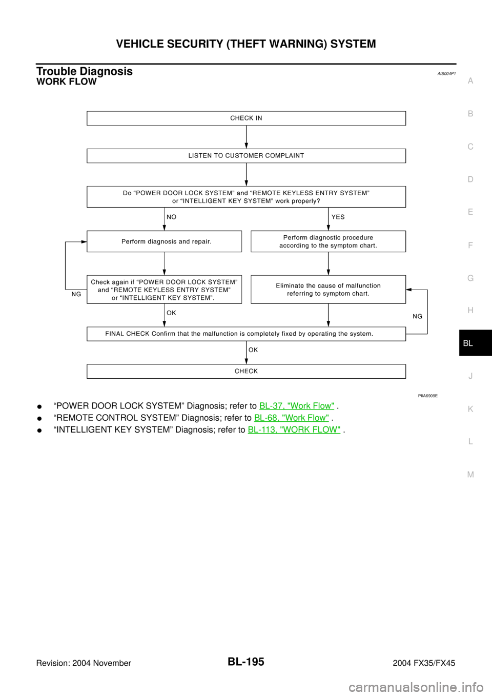
Trouble DiagnosisAIS004P1
WORK FLOW
�“POWER DOOR LOCK SYSTEM” Diagnosis; refer to BL-37, "Work Flow" .
�“REMOTE CONTROL SYSTEM” Diagnosis; refer to BL-68, "Work Flow" .
�“INTELLIGENT KEY SYSTEM” Diagnosis; refer to BL-113, "WORK FLOW" .
PIIA6909E
Page 1015 of 4449

Revision: 2004 November 2004 FX35/FX45
System CompositionAIS004PC
The immobilizer function of the IVIS (NATS) consists of the following:
�Ignitio")
BL-208
IVIS (INFINITI VEHICLE IMMOBILIZER SYSTEM-NATS)
Revision: 2004 November 2004 FX35/FX45
System CompositionAIS004PC
The immobilizer function of the IVIS (NATS) consists of the following:
�Ignition key (models without Intelligent Key system)
�Mechanical key (models with Intelligent Key system)
�NATS antenna amp.
�Steering lock unit. (models with Intelligent Key system)
�BCM
�Intelligent Key unit (models with Intelligent Key system)
�Engine control module (ECM)
�Security indicator
NOTE:
The communication between ECM, BCM and/or Intelligent Key unit uses the CAN communication sys-
tem.
ECM Re-communicating FunctionAIS004PD
Performing following procedure can automatically perform re-communication of ECM and BCM or Intelligent
Key unit, but only when the ECM has been replaced with a new one (*1).
*1: New one means a virgin ECM which has never been energized on-board.
(In this step, initialization procedure by CONSULT-II is not necessary)
NOTE:
�When registering new Key IDs or replacing the ECM other than brand new, refer to CONSULT-II
Operation Manual NATS-IVIS/NVIS.
�If multiple keys are attached to the key holder, separate them before work.
�Distinguish keys with unregistered key ID from those with registered ID.
1. Install ECM.
2. Using a registered key (*2), turn ignition switch to “ON”.
*2: To perform this step, use the key that has been used before performing ECM replacement.
3. Maintain ignition switch in “ON” position for at least 5 seconds.
4. Turn ignition switch to “OFF”.
5. Start engine.
If engine can be started, procedure is completed.
If engine cannot be started, refer to CONSULT-II Operation Manual NATS-IVIS/NVIS and initialize control
unit.
PIIA6948E
Page 1021 of 4449
BL-214
IVIS (INFINITI VEHICLE IMMOBILIZER SYSTEM-NATS)
Revision: 2004 November 2004 FX35/FX45
CONSULT-IIAIS004PI
CONSULT-II INSPECTION PROCEDURE
CAUTION:
If CONSULT-II is used with no connection CONSULT-II CONVERTER, malfunctions might be detected
in self-diagnosis depending on control unit which carry out CAN Communication.
1. Turn ignition switch OFF.
2. Insert IVIS (NATS) program card into CONSULT-II.
3. Connect CONSULT-II and “CONSULT-II CONVERTER” to data
link connector.
4. Turn ignition switch ON.
5. Touch “START”.
6. Touch “OTHER”.
7. Perform each diagnostic test mode according to each service
procedure.
For further information, see the CONSULT-II Operation Manual,
NATS-IVIS/NVIS.Program card : NATS (AEN02C)
PBIB0196E
PBR455D
PIIA6816E
SEL150X
Page 1022 of 4449
IVIS (INFINITI VEHICLE IMMOBILIZER SYSTEM-NATS)
BL-215
C
D
E
F
G
H
J
K
L
MA
B
BL
Revision: 2004 November 2004 FX35/FX45
CONSULT-II DIAGNOSTIC TEST MODE FUNCTION
NOTE:
When any initialization is performed, all ID numbers previously registered will be erased and all ignition key or
mechanical key must be registered again. The engine cannot be started with an unregistered key. The system
will show “DIFFERENCE OF KEY” or “LOCK MODE” as a self-diagnostic result on the CONSULT-II screen.
HOW TO READ SELF-DIAGNOSTIC RESULTS
CONSULT- II DIAGNOSTIC TEST MODE Description
C/U INITIALIZATIONWhen replacing any of the following three components, C/U initialization is necessary.
[IVIS (NATS) ignition key/ BCM/ ECM]
SELF- DIAGNOSTIC RESULTS Detected items (screen terms) are as shown in the chart.
PIN READIndividual control unit number can be read.
For future information, refer to operation manual NATS-IVIS/NVIS
PIIA1124E
Page 1096 of 4449
 “AIR BAG” and “SEAT
BELT PRE-TENSIONER")
PRECAUTIONS
BR-3
C
D
E
G
H
I
J
K
L
MA
B
BR
Revision: 2004 November 2004 FX35/FX45
PRECAUTIONSPFP:00001
Precautions for Supplemental Restraint System (SRS) “AIR BAG” and “SEAT
BELT PRE-TENSIONER”
AFS0028A
The Supplemental Restraint System such as “AIR BAG” and “SEAT BELT PRE-TENSIONER”, used along
with a front seat belt, helps to reduce the risk or severity of injury to the driver and front passenger for certain
types of collision. This system includes seat belt switch inputs and dual stage front air bag modules. The SRS
system uses the seat belt switches to determine the front air bag deployment, and may only deploy one front
air bag, depending on the severity of a collision and whether the front occupants are belted or unbelted.
Information necessary to service the system safely is included in the SRS and SB section of this Service Man-
ual.
WARNING:
�To avoid rendering the SRS inoperative, which could increase the risk of personal injury or death
in the event of a collision which would result in air bag inflation, all maintenance must be per-
formed by an authorized NISSAN/INFINITI dealer.
�Improper maintenance, including incorrect removal and installation of the SRS, can lead to per-
sonal injury caused by unintentional activation of the system. For removal of Spiral Cable and Air
Bag Module, see the SRS section.
�Do not use electrical test equipment on any circuit related to the SRS unless instructed to in this
Service Manual. SRS wiring harnesses can be identified by yellow and/or orange harnesses or
harness connectors.
Precautions for Brake SystemAFS001MQ
�Recommended fluid is brake fluid “DOT 3”.
�Do not reuse drained brake fluid.
�Be careful not to splash brake fluid on painted areas.
�To clean or wash all parts of master cylinder, disc brake caliper and wheel cylinder, use clean brake fluid.
�Do not use mineral oils such as gasoline or kerosene. They will ruin rubber parts of the hydraulic system.
�Use flare nut wrench when removing and installing brake tube.
�When installing brake piping, be sure to check torque.
�Before working, turn ignition switch OFF and disconnect con-
nectors for ABS actuator and electric unit (control unit) or battery
terminal.
�Burnish the brake contact surfaces after refinishing or replacing
drums or rotors, after replacing pads or linings, or if a soft pedal
occurs at very low mileage.
Refer to BR-24, "
BRAKE BURNISHING PROCEDURE" .
WARNING:
�Clean brake pads and shoes with a waste cloth, then wipe
with a dust collector.SBR686C
 SYSTEM
BL-185
C
D
E
F
G
H
J
K
L
MA
B
BL
Revision: 2004 November 2004 FX35/FX45
CAN Communication System DescriptionAIS004OU
CAN (Controller Area Network) is a serial c")
 SYSTEM
BL-193
C
D
E
F
G
H
J
K
L
MA
B
BL
Revision: 2004 November 2004 FX35/FX45
CONSULT-II Inspection ProcedureAIS004P0
CAUTION:
CONSULT-II is used with no connection o")

Revision: 2004 November 2004 FX35/FX45
CONSULT-IIAIS004PI
CONSULT-II INSPECTION PROCEDURE
CAUTION:
If CONSULT-II is used with no connection CONSU")

BL-215
C
D
E
F
G
H
J
K
L
MA
B
BL
Revision: 2004 November 2004 FX35/FX45
CONSULT-II DIAGNOSTIC TEST MODE FUNCTION
NOTE:
When any initialization is perfor")