Page 3964 of 4449
POWER STEERING OIL PUMP
PS-31
C
D
E
F
H
I
J
K
L
MA
B
PS
Revision: 2004 November 2004 FX35/FX45
POWER STEERING OIL PUMPPFP:49110
On-Vehicle Inspection and ServiceAGS000H2
CHECKING RELIEF OIL PRESSURE (VQ35DE MODELS)
CAUTION:
Before starting work, confirm belt tension is proper.
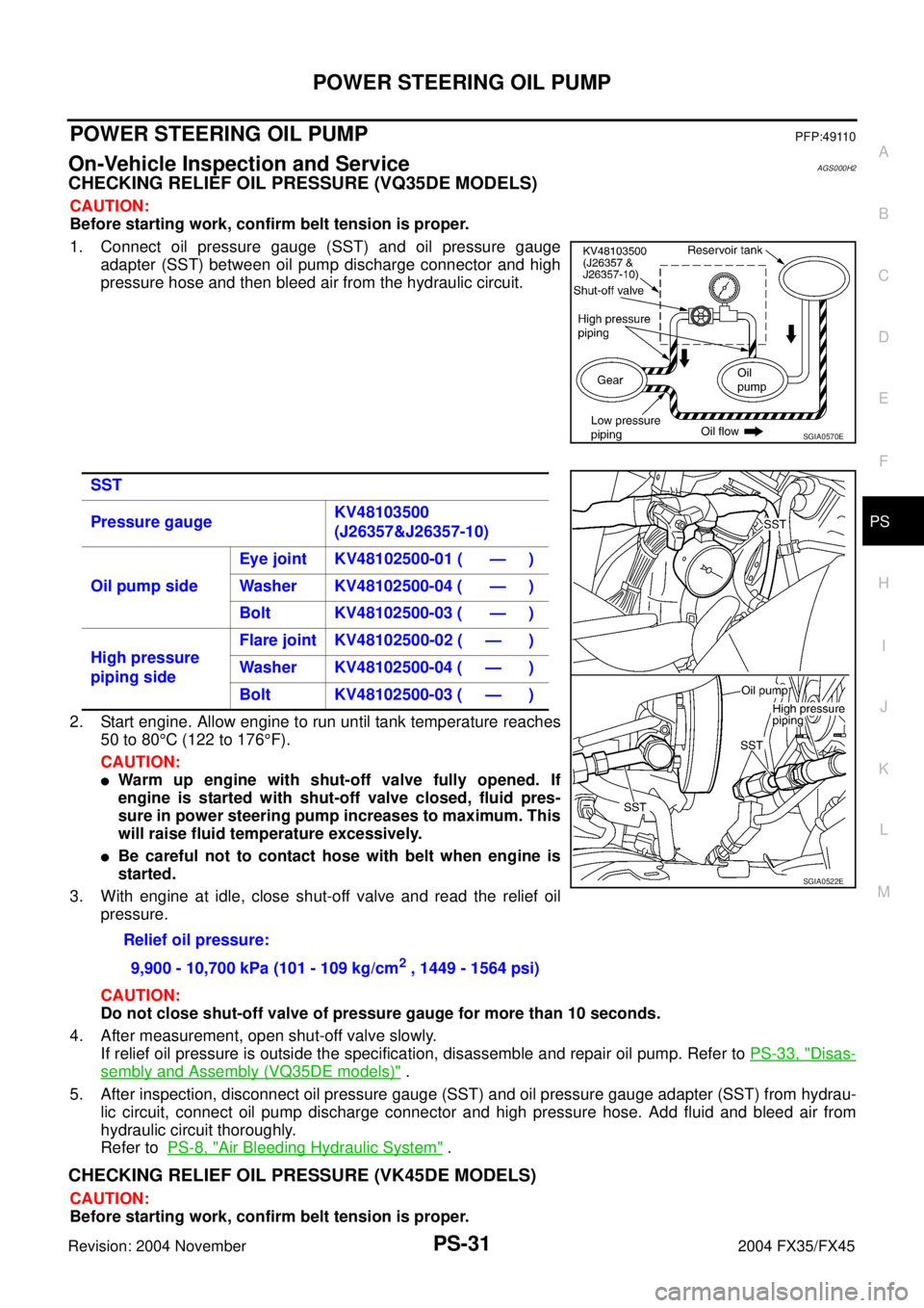
1. Connect oil pressure gauge (SST) and oil pressure gauge
adapter (SST) between oil pump discharge connector and high
pressure hose and then bleed air from the hydraulic circuit.
2. Start engine. Allow engine to run until tank temperature reaches
50 to 80°C (122 to 176°F).
CAUTION:
�Warm up engine with shut-off valve fully opened. If
engine is started with shut-off valve closed, fluid pres-
sure in power steering pump increases to maximum. This
will raise fluid temperature excessively.
�Be careful not to contact hose with belt when engine is
started.
3. With engine at idle, close shut-off valve and read the relief oil
pressure.
CAUTION:
Do not close shut-off valve of pressure gauge for more than 10 seconds.
4. After measurement, open shut-off valve slowly.
If relief oil pressure is outside the specification, disassemble and repair oil pump. Refer to PS-33, "
Disas-
sembly and Assembly (VQ35DE models)" .
5. After inspection, disconnect oil pressure gauge (SST) and oil pressure gauge adapter (SST) from hydrau-
lic circuit, connect oil pump discharge connector and high pressure hose. Add fluid and bleed air from
hydraulic circuit thoroughly.
Refer to PS-8, "
Air Bleeding Hydraulic System" .
CHECKING RELIEF OIL PRESSURE (VK45DE MODELS)
CAUTION:
Before starting work, confirm belt tension is proper.
SGIA0570E
SST
Pressure gaugeKV48103500
(J26357&J26357-10)
Oil pump sideEye joint KV48102500-01 ( — )
Washer KV48102500-04 ( — )
Bolt KV48102500-03 ( — )
High pressure
piping sideFlare joint KV48102500-02 ( — )
Washer KV48102500-04 ( — )
Bolt KV48102500-03 ( — )
Relief oil pressure:
9,900 - 10,700 kPa (101 - 109 kg/cm
2 , 1449 - 1564 psi)
SGIA0522E
Page 4309 of 4449
TF-8
TRANSFER FLUID
Revision: 2004 November 2004 FX35/FX45
TRANSFER FLUIDPFP:31001
ReplacementADS000RN
DRAINING
1. Run the vehicle to warm up the transfer unit sufficiently.
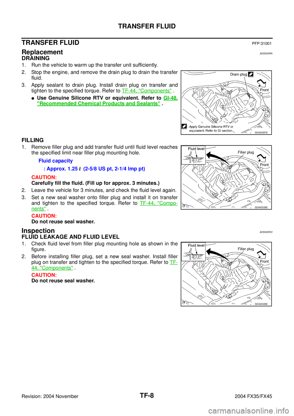
2. Stop the engine, and remove the drain plug to drain the transfer
fluid.
3. Apply sealant to drain plug. Install drain plug on transfer and
tighten to the specified torque. Refer to TF-44, "
Components" .
�Use Genuine Silicone RTV or equivalent. Refer to GI-48,
"Recommended Chemical Products and Sealants" .
FILLING
1. Remove filler plug and add transfer fluid until fluid level reaches
the specified limit near filler plug mounting hole.
CAUTION:
Carefully fill the fluid. (Fill up for approx. 3 minutes.)
2. Leave the vehicle for 3 minutes, and check the fluid level again.
3. Set a new seal washer onto filler plug and install it on transfer
and tighten to the specified torque. Refer to TF-44, "
Compo-
nents" .
CAUTION:
Do not reuse seal washer.
InspectionADS000RO
FLUID LEAKAGE AND FLUID LEVEL
1. Check fluid level from filler plug mounting hole as shown in the
figure.
2. Before installing filler plug, set a new seal washer. Install filler
plug on transfer and tighten to the specified torque. Refer to TF-
44, "Components" .
CAUTION:
Do not reuse seal washer.
SDIA2087E
Fluid capacity
: Approx. 1.25 (2-5/8 US pt, 2-1/4 lmp pt)
SDIA2028E
SDIA2028E
Page 4420 of 4449
FRONT WIPER AND WASHER SYSTEM
WW-29
C
D
E
F
G
H
I
J
L
MA
B
WW
Revision: 2004 November 2004 FX35/FX45
2. Prior to wiper arm installation, turn on wiper switch to operate
wiper motor and then turn it “OFF” (auto stop).
3. Push wiper arm onto pivot shaft, paying attention to blind spline.
4. Attach washer tube to washer tube joint.
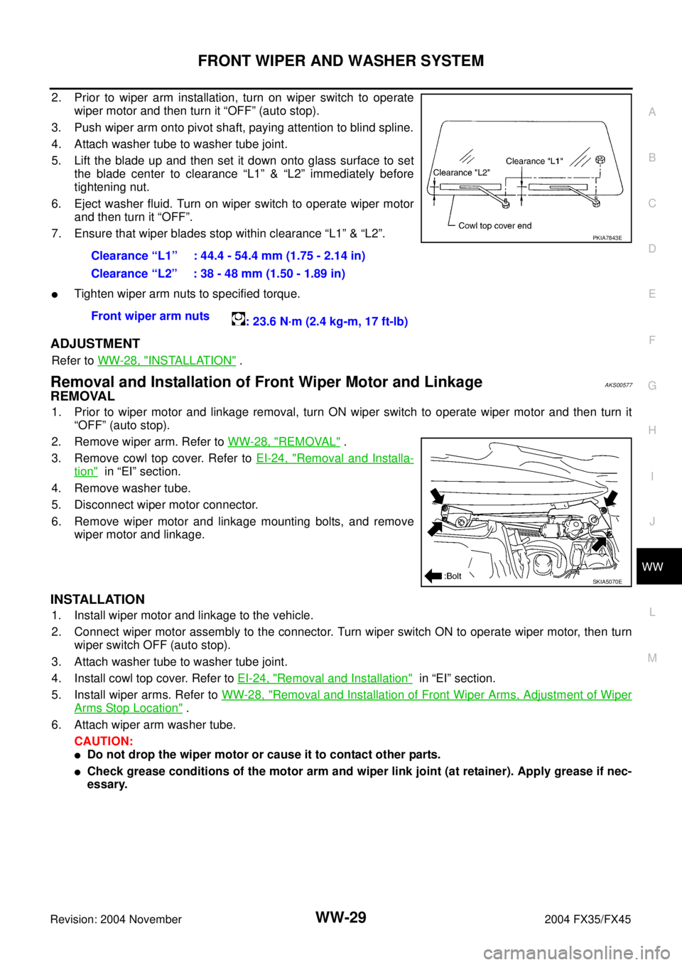
5. Lift the blade up and then set it down onto glass surface to set
the blade center to clearance “L1” & “L2” immediately before
tightening nut.
6. Eject washer fluid. Turn on wiper switch to operate wiper motor
and then turn it “OFF”.
7. Ensure that wiper blades stop within clearance “L1” & “L2”.
�Tighten wiper arm nuts to specified torque.
ADJUSTMENT
Refer to WW-28, "INSTALLATION" .
Removal and Installation of Front Wiper Motor and LinkageAKS00577
REMOVAL
1. Prior to wiper motor and linkage removal, turn ON wiper switch to operate wiper motor and then turn it
“OFF” (auto stop).
2. Remove wiper arm. Refer to WW-28, "
REMOVAL" .
3. Remove cowl top cover. Refer to EI-24, "
Removal and Installa-
tion" in “EI” section.
4. Remove washer tube.
5. Disconnect wiper motor connector.
6. Remove wiper motor and linkage mounting bolts, and remove
wiper motor and linkage.
INSTALLATION
1. Install wiper motor and linkage to the vehicle.
2. Connect wiper motor assembly to the connector. Turn wiper switch ON to operate wiper motor, then turn
wiper switch OFF (auto stop).
3. Attach washer tube to washer tube joint.
4. Install cowl top cover. Refer to EI-24, "
Removal and Installation" in “EI” section.
5. Install wiper arms. Refer to WW-28, "
Removal and Installation of Front Wiper Arms, Adjustment of Wiper
Arms Stop Location" .
6. Attach wiper arm washer tube.
CAUTION:
�Do not drop the wiper motor or cause it to contact other parts.
�Check grease conditions of the motor arm and wiper link joint (at retainer). Apply grease if nec-
essary.Clearance “L1” : 44.4 - 54.4 mm (1.75 - 2.14 in)
Clearance “L2” : 38 - 48 mm (1.50 - 1.89 in)
Front wiper arm nuts
: 23.6 N·m (2.4 kg-m, 17 ft-lb)
PKIA7843E
SKIA5070E
Page 4424 of 4449
FRONT WIPER AND WASHER SYSTEM
WW-33
C
D
E
F
G
H
I
J
L
MA
B
WW
Revision: 2004 November 2004 FX35/FX45
Removal and Installation of Front Wiper and Washer SwitchAKS0057E
REMOVAL
1. Remove steering column upper cover. Refer to IP-14, "(N)
Steering Column Upper Cover" in “IP” section.
2. Disconnect wiper and washer switch connector.
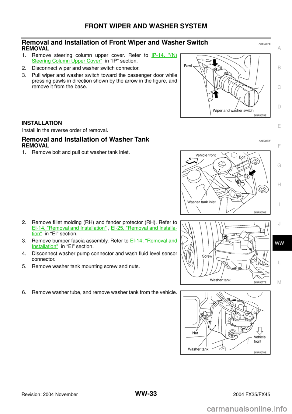
3. Pull wiper and washer switch toward the passenger door while
pressing pawls in direction shown by the arrow in the figure, and
remove it from the base.
INSTALLATION
Install in the reverse order of removal.
Removal and Installation of Washer TankAKS0057F
REMOVAL
1. Remove bolt and pull out washer tank inlet.
2. Remove fillet molding (RH) and fender protector (RH). Refer to
EI-14, "
Removal and Installation" , EI-25, "Removal and Installa-
tion" in “EI” section.
3. Remove bumper fascia assembly. Refer to EI-14, "
Removal and
Installation" in “EI” section.
4. Disconnect washer pump connector and wash fluid level sensor
connector.
5. Remove washer tank mounting screw and nuts.
6. Remove washer tube, and remove washer tank from the vehicle.
SKIA5075E
SKIA5076E
SKIA5077E
SKIA5078E
Page 4439 of 4449
WW-48
REAR WIPER AND WASHER SYSTEM
Revision: 2004 November 2004 FX35/FX45
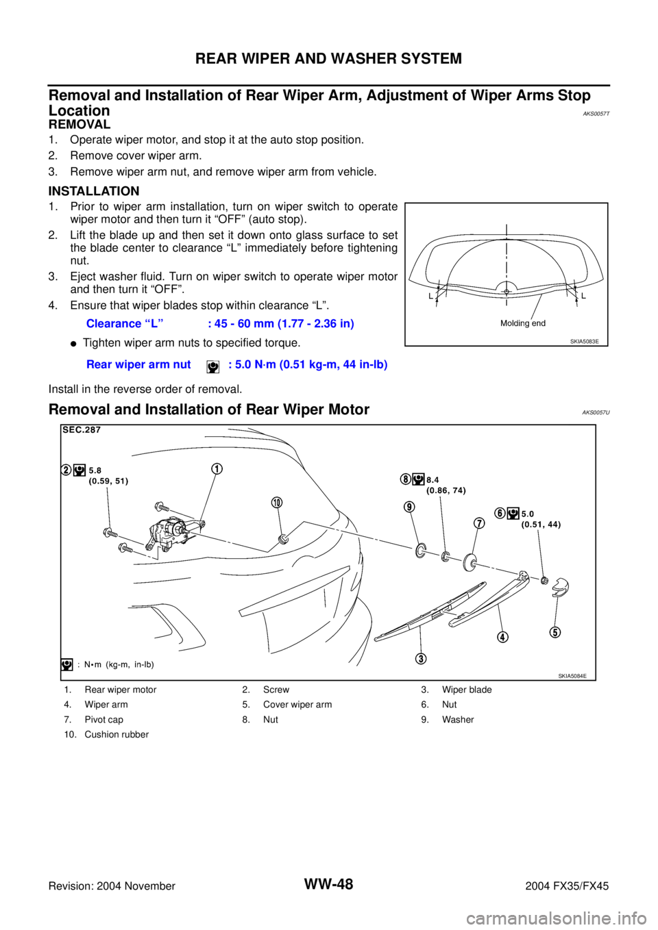
Removal and Installation of Rear Wiper Arm, Adjustment of Wiper Arms Stop
Location
AKS0057T
REMOVAL
1. Operate wiper motor, and stop it at the auto stop position.
2. Remove cover wiper arm.
3. Remove wiper arm nut, and remove wiper arm from vehicle.
INSTALLATION
1. Prior to wiper arm installation, turn on wiper switch to operate
wiper motor and then turn it “OFF” (auto stop).
2. Lift the blade up and then set it down onto glass surface to set
the blade center to clearance “L” immediately before tightening
nut.
3. Eject washer fluid. Turn on wiper switch to operate wiper motor
and then turn it “OFF”.
4. Ensure that wiper blades stop within clearance “L”.
�Tighten wiper arm nuts to specified torque.
Install in the reverse order of removal.
Removal and Installation of Rear Wiper Motor AKS0057U
Clearance “L” : 45 - 60 mm (1.77 - 2.36 in)
Rear wiper arm nut : 5.0 N·m (0.51 kg-m, 44 in-lb)
SKIA5083E
1. Rear wiper motor 2. Screw 3. Wiper blade
4. Wiper arm 5. Cover wiper arm 6. Nut
7. Pivot cap 8. Nut 9. Washer
10. Cushion rubber
SKIA5084E
Page 4442 of 4449
REAR WIPER AND WASHER SYSTEM
WW-51
C
D
E
F
G
H
I
J
L
MA
B
WW
Revision: 2004 November 2004 FX35/FX45
Check Valve InspectionAKS0057X
A check valve is provided in the washer fluid line. Be careful not to
connect check valve to washer tube in the wrong direction.
Removal and Installation of Rear Wiper and Washer SwitchAKS0057Y
Refer to WW-33, "Removal and Installation of Front Wiper and Washer Switch" .
Removal and Installation of Washer TankAKS0057Z
Refer to WW-33, "Removal and Installation of Washer Tank" .
Removal and Installation of Washer PumpAKS00580
Refer to WW-34, "Removal and Installation of Washer Motor" .
SEL411H