Page 1115 of 4449

BR-22
FRONT DISC BRAKE
Revision: 2004 November 2004 FX35/FX45
2. Install caliper assembly to the vehicle, and tighten bolts to the
specified torque.
CAUTION:
When attaching caliper assembly to the vehicle, wipe any
oil off knuckle spindle, washers and caliper assembly
attachment surfaces.
3. Install brake hose to brake caliper assembly, and tighten union
bolt to the specified torque.
CAUTION:
�Do not reuse copper washers for union bolt.
�Attach brake hose to caliper assembly together with
union bolt and washers.
4. Refill new brake fluid and bleed air. Refer to BR-10, "
Bleeding Brake System" .
5. Attach tires to the vehicle.
Disassembly and Assembly of Brake Caliper AssemblyAFS001S1
DISASSEMBLY
1. Remove sliding pin bolt, and then remove the pad, shim, shim cover, and pad retainer from the torque
member.
2. Remove sliding pins and sliding pin boots from torque member.
3. Place a wooden block as shown in the figure, and blow air from
union bolt mounting hole to remove pistons and piston boots.
CAUTION:
Do not get your fingers caught in piston.
4. Using a flat-bladed screwdriver, remove piston seal from cylin-
der body.
CAUTION:
Be careful not to damage cylinder inner wall.
SFIA1205E
SFIA1204E
MAA0272D
SFIA1301E
Page 1120 of 4449

REAR DISC BRAKE
BR-27
C
D
E
G
H
I
J
K
L
MA
B
BR
Revision: 2004 November 2004 FX35/FX45
CAUTION:
Before installing caliper assembly to the vehicle, wipe off oil and grease on washer seats on axle
assembly and mounting surface of caliper assembly.
3. Install brake hose to caliper assembly and tighten union bolt to the specified torque.
CAUTION:
�Do not reuse copper washer for union bolt.
�Securely attach brake hose to protrusion on caliper assembly.
4. Refill new brake fluid and bleed air. Refer to BR-10, "
Bleeding Brake System" .
5. Install tires to the vehicle.
Disassembly and Assembly of Brake Caliper AssemblyAFS001NE
DISASSEMBLY
1. Remove sliding pin bolt, and then remove pad, shim, shim cover, and pad retainer from torque member
and cylinder.
2. Remove sliding pin boot from torque member.
3. As shown in the figure, using a flat-bladed screwdriver, remove
retaining ring from cylinder body.
4. Place a wooden block as shown in the figure, and blow air from
union bolt mounting hole to remove pistons and piston boots.
CAUTION:
Do not get your fingers caught in piston.
5. Using a flat-bladed screwdriver, remove piston seals from cylin-
der body.
CAUTION:
Be careful not to damage cylinder inner wall.
CALIPER INSPECTION
Cylinder Body
CAUTION:
�Use new brake fluid to clean. Do not use mineral oils such as gasoline or kerosene.
�Check inside surface of cylinder for score, rust wear, damage or foreign materials. If any of the
above conditions are observed, replace cylinder body.
SBR028A
BRD0041D
PFIA0269E
Page 1206 of 4449
RADIATOR (ALUMINUM TYPE)
CO-17
[VQ35DE]
C
D
E
F
G
H
I
J
K
L
MA
CO
Revision: 2004 November 2004 FX35/FX45
RADIATOR (ALUMINUM TYPE)PFP:21460
Disassembly and AssemblyABS004VZ
PREPARATION
1. Attach spacer to the tip of radiator plate pliers A (SST).
Spacer specification: 1.5 mm (0.059 in) thick x 18 mm (0.71 in)
wide x 8.5 mm (0.335 in) long.
2. Make sure that when radiator plate pliers A (SST) are closed
dimension H′′ is approx. 7.6 mm (0.299 in).
3. Adjust dimension H′′ with spacer, if necessary.
DISASSEMBLY
1. Remove upper or lower tanks with radiator plate pliers B (SST).
1. Upper tank 2. Sealing rubber 3. Core
4. Lower tank 5. Conical washer 6. Washer
7. O-ring 8. A/T fluid cooler
SBIA0449E
SLC655CB
SLC903-A
Page 1207 of 4449
CO-18
[VQ35DE]
RADIATOR (ALUMINUM TYPE)
Revision: 2004 November 2004 FX35/FX45
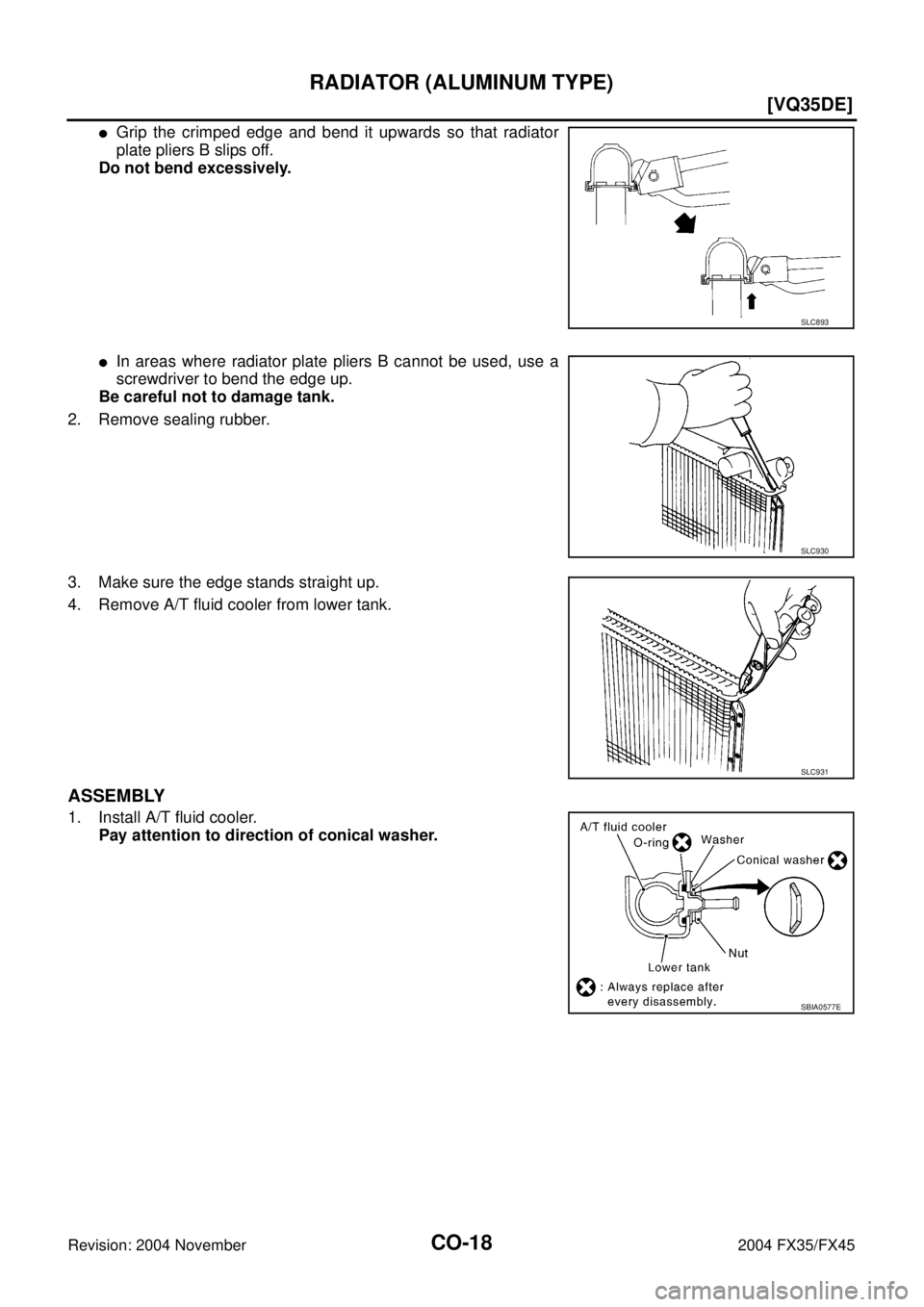
�Grip the crimped edge and bend it upwards so that radiator
plate pliers B slips off.
Do not bend excessively.
�In areas where radiator plate pliers B cannot be used, use a
screwdriver to bend the edge up.
Be careful not to damage tank.
2. Remove sealing rubber.
3. Make sure the edge stands straight up.
4. Remove A/T fluid cooler from lower tank.
ASSEMBLY
1. Install A/T fluid cooler.
Pay attention to direction of conical washer.
SLC893
SLC930
SLC931
SBIA0577E
Page 1217 of 4449
![INFINITI FX35 2004 Service Manual CO-28
[VQ35DE]
WATER OUTLET AND WATER PIPING
Revision: 2004 November 2004 FX35/FX45
WATER OUTLET AND WATER PIPINGPFP:11060
Removal and InstallationABS007ZU
REMOVAL
1. Remove front engine undercover wi](/manual-img/42/57021/w960_57021-1216.png "INFINITI FX35 2004 Service Manual CO-28
[VQ35DE]
WATER OUTLET AND WATER PIPING
Revision: 2004 November 2004 FX35/FX45
WATER OUTLET AND WATER PIPINGPFP:11060
Removal and InstallationABS007ZU
REMOVAL
1. Remove front engine undercover wi")
CO-28
[VQ35DE]
WATER OUTLET AND WATER PIPING
Revision: 2004 November 2004 FX35/FX45
WATER OUTLET AND WATER PIPINGPFP:11060
Removal and InstallationABS007ZU
REMOVAL
1. Remove front engine undercover with power tool.
2. Drain engine coolant from drain plug and water drain plugs on radiator and both sides of cylinder block.
Refer to CO-11, "
Changing Engine Coolant" .
CAUTION:
Perform when engine is cold.
3. Remove engine cover with power tool. Refer to EM-19, "
INTAKE MANIFOLD COLLECTOR" .
4. Remove air duct and air cleaner case assembly. Refer to EM-17, "
AIR CLEANER AND AIR DUCT" .
5. Disconnect radiator upper hose, heater hose and water hose.
6. Remove water outlet and water piping.
INSTALLATION
Note to the following, and install in the reverse order of removal.
�Securely insert each hose, and install a clamp at a position where it does not interfere with the pipe bulge.
�When inserting a water pipe into water outlet, apply neutral detergent to O-ring.
INSPECTION AFTER INSTALLATION
�Check for leaks of engine coolant using radiator cap tester adapter [SST: EG17650301 (J-33984-A)] and
radiator cap tester (commercial service tool). Refer to CO-11, "
CHECKING COOLING SYSTEM FOR
LEAKS" .
�Start and warm up engine. Visually make sure that there is no leaks of engine coolant and A/T fluid.
1. Harness bracket 2. Water hose 3. Water bypass hose
4. Engine coolant temperature sensor 5. Gasket 6. Water outlet
7. Heater hose 8. Water pipe 9. Radiator upper hose
10. Heater pipe 11. Washer 12. O-ring
SBIA0484E
Page 1229 of 4449
CO-40
[VK45DE]
RADIATOR
Revision: 2004 November 2004 FX35/FX45
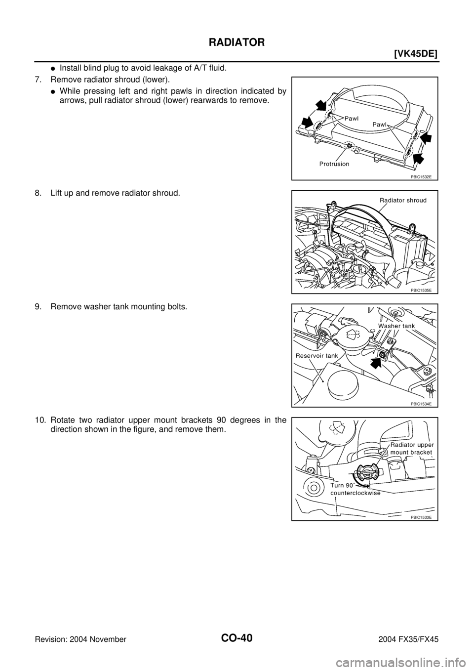
�Install blind plug to avoid leakage of A/T fluid.
7. Remove radiator shroud (lower).
�While pressing left and right pawls in direction indicated by
arrows, pull radiator shroud (lower) rearwards to remove.
8. Lift up and remove radiator shroud.
9. Remove washer tank mounting bolts.
10. Rotate two radiator upper mount brackets 90 degrees in the
direction shown in the figure, and remove them.
PBIC1532E
PBIC1535E
PBIC1534E
PBIC1533E
Page 1233 of 4449
CO-44
[VK45DE]
RADIATOR (ALUMINUM TYPE)
Revision: 2004 November 2004 FX35/FX45
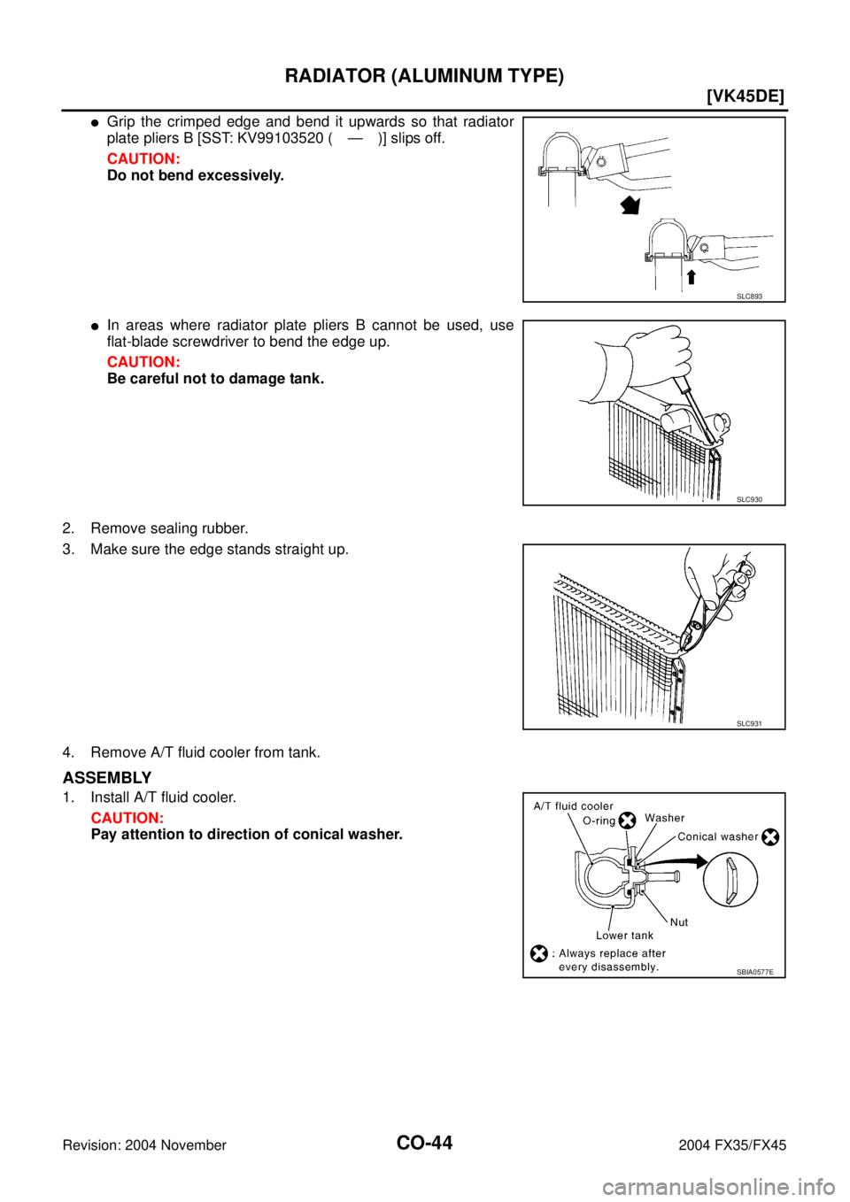
�Grip the crimped edge and bend it upwards so that radiator
plate pliers B [SST: KV99103520 ( — )] slips off.
CAUTION:
Do not bend excessively.
�In areas where radiator plate pliers B cannot be used, use
flat-blade screwdriver to bend the edge up.
CAUTION:
Be careful not to damage tank.
2. Remove sealing rubber.
3. Make sure the edge stands straight up.
4. Remove A/T fluid cooler from tank.
ASSEMBLY
1. Install A/T fluid cooler.
CAUTION:
Pay attention to direction of conical washer.
SLC893
SLC930
SLC931
SBIA0577E
Page 3108 of 4449

PRECAUTIONS
GI-5
C
D
E
F
G
H
I
J
K
L
MB
GI
Revision: 2004 November 2004 FX35/FX45
�Before starting repairs which do not require battery power:
Turn off ignition switch.
Disconnect the negative battery terminal.
�If the battery terminals are disconnected, recorded memory of
radio and each control unit is erased.
�To prevent serious burns:
Avoid contact with hot metal parts.
Do not remove the radiator cap when the engine is hot.
�Dispose of drained oil or the solvent used for cleaning parts in
an appropriate manner.
�Do not attempt to top off the fuel tank after the fuel pump nozzle
shuts off automatically.
Continued refueling may cause fuel overflow, resulting in fuel
spray and possibly a fire.
�Clean all disassembled parts in the designated liquid or solvent
prior to inspection or assembly.
�Replace oil seals, gaskets, packings, O-rings, locking washers, cotter pins, self-locking nuts, etc. with new
ones.
�Replace inner and outer races of tapered roller bearings and needle bearings as a set.
�Arrange the disassembled parts in accordance with their assembled locations and sequence.
�Do not touch the terminals of electrical components which use microcomputers (such as ECM).
Static electricity may damage internal electronic components.
�After disconnecting vacuum or air hoses, attach a tag to indicate the proper connection.
�Use only the fluids and lubricants specified in this manual.
�Use approved bonding agent, sealants or their equivalents when required.
�Use hand tools, power tools (disassembly only) and recom-
mended special tools where specified for safe and efficient ser-
vice repairs.
�When repairing the fuel, oil, water, vacuum or exhaust systems,
check all affected lines for leaks.
�Before servicing the vehicle:
Protect fenders, upholstery and carpeting with appropriate cov-
ers.
Take caution that keys, buckles or buttons do not scratch paint.
SEF289H
SGI233
PBIC0190E
SGI234
![INFINITI FX35 2004 Service Manual RADIATOR (ALUMINUM TYPE)
CO-17
[VQ35DE]
C
D
E
F
G
H
I
J
K
L
MA
CO
Revision: 2004 November 2004 FX35/FX45
RADIATOR (ALUMINUM TYPE)PFP:21460
Disassembly and AssemblyABS004VZ
PREPARATION
1. Attach spacer](/manual-img/42/57021/w960_57021-1205.png "INFINITI FX35 2004 Service Manual RADIATOR (ALUMINUM TYPE)
CO-17
[VQ35DE]
C
D
E
F
G
H
I
J
K
L
MA
CO
Revision: 2004 November 2004 FX35/FX45
RADIATOR (ALUMINUM TYPE)PFP:21460
Disassembly and AssemblyABS004VZ
PREPARATION
1. Attach spacer")