Page 503 of 4449

ATC-74
TROUBLE DIAGNOSIS
Revision: 2004 November 2004 FX35/FX45
SYSTEM DESCRIPTION
Component Parts
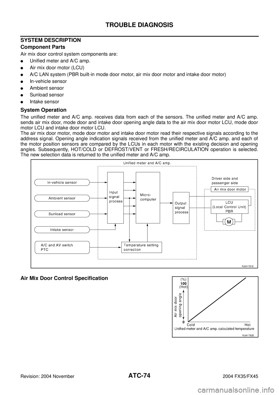
Air mix door control system components are:
�Unified meter and A/C amp.
�Air mix door motor (LCU)
�A/C LAN system (PBR built-in mode door motor, air mix door motor and intake door motor)
�In-vehicle sensor
�Ambient sensor
�Sunload sensor
�Intake sensor
System Operation
The unified meter and A/C amp. receives data from each of the sensors. The unified meter and A/C amp.
sends air mix door, mode door and intake door opening angle data to the air mix door motor LCU, mode door
motor LCU and intake door motor LCU.
The air mix door motor, mode door motor and intake door motor read their respective signals according to the
address signal. Opening angle indication signals received from the unified meter and A/C amp. and each of
the motor position sensors are compared by the LCUs in each motor with the existing decision and opening
angles. Subsequently, HOT/COLD or DEFROST/VENT or FRESH/RECIRCULATION operation is selected.
The new selection data is returned to the unified meter and A/C amp.
Air Mix Door Control Specification
RJIA1781E
RJIA1782E
Page 505 of 4449
ATC-76
TROUBLE DIAGNOSIS
Revision: 2004 November 2004 FX35/FX45
Intake Door Motor CircuitAJS0014W
SYMPTOM:
�Intake door does not change.
�Intake door motor does not operate normally.
INSPECTION FLOW
*1AT C - 5 4 , "FUNCTION CONFIRMA-
TION PROCEDURE", see No. 4 to 6.*2ATC-104, "
Ambient Sensor Circuit".*3ATC-107, "In-vehicle Sensor Circuit".
*4AT C - 11 0 , "
Sunload Sensor Circuit".*5AT C - 7 3 , "Air Mix Door Motor Cir-
cuit".*6AT C - 5 4 , "
FUNCTION CONFIRMA-
TION PROCEDURE", see No. 13.
*7AT C - 6 6 , "
LAN System Circuit".*8ATC-124, "INTAKE DOOR
MOTOR".*9AT C - 6 1 , "
Operational Check".
*10AT C - 4 2 , "
SYMPTOM TABLE".*11AT C - 11 3 , "Intake Sensor Circuit".
RJIA1993E
Page 506 of 4449
TROUBLE DIAGNOSIS
ATC-77
C
D
E
F
G
H
I
K
L
MA
B
AT C
Revision: 2004 November 2004 FX35/FX45
SYSTEM DESCRIPTION
Component Parts
Intake door control system components are:
�Unified meter and A/C amp.
�Intake door motor (LCU)
�A/C LAN system (PBR built-in mode door motor, air mix door motor and intake door motor)
�In-vehicle sensor
�Ambient sensor
�Sunload sensor
�Intake sensor
System Operation
The intake door control determines intake door position based on the ambient temperature, the intake air tem-
perature and the in-vehicle temperature. When the DEFROST, or OFF switches are pushed or A/C switch is
OFF, the unified meter and A/C amp. sets the intake door at the FRESH position.
Intake Door Control Specification
RJIA1786E
RJIA1787E
Page 509 of 4449

ATC-80
TROUBLE DIAGNOSIS
Revision: 2004 November 2004 FX35/FX45
SYSTEM DESCRIPTION
Component Parts
Fan speed control system components are:
�Unified meter and A/C amp.
�A/C LAN system (PBR built-in mode door motor, air mix door motor and intake door motor)
�In-vehicle sensor
�Ambient sensor
�Sunload sensor
�Intake sensor
System Operation
Automatic Mode
In the automatic mode, the blower motor speed is calculated by the unified meter and A/C amp. based on
input from the PBR, in-vehicle sensor, sunload sensor, intake sensor and ambient sensor.
When the air flow is increased, the duty ratio of the blower fan motor′s drive signal is changed at 8%/sec. to
prevent a sudden increase in air flow.
In addition to manual air flow control and the usual automatic air flow control, starting air flow control, low
water temperature starting control and high passenger compartment temperature starting control are avail-
able.
*7AT C - 4 2 , "SYMPTOM TABLE".*8ATC-104, "Ambient Sensor Circuit".*9ATC-107, "In-vehicle Sensor Cir-
cuit".
*10AT C - 11 0 , "
Sunload Sensor Circuit".*11EC-185, "DTC P0117, P0118 ECT
SENSOR" (VQ35DE) or EC-842,
"DTC P0117, P0118 ECT SEN-
SOR" (VK45DE).
RJIA1995E
Page 521 of 4449
ATC-92
TROUBLE DIAGNOSIS
Revision: 2004 November 2004 FX35/FX45
*1ATC-54, "FUNCTION CONFIRMA-
TION PROCEDURE", see No. 4 to 6.*2ATC-73, "
Air Mix Door Motor Circuit".*3ATC-95, "Test Reading".
*4ATC-59, "
AUXILIARY MECHA-
NISM: TEMPERATURE SETTING
TRIMMER".*5ATC-54, "
FUNCTION CONFIRMA-
TION PROCEDURE", see No. 13.*6ATC-66, "
LAN System Circuit".
*7ATC-79, "
Blower Motor Circuit".*8ATC-84, "Magnet Clutch Circuit".*9ATC-93, "PERFORMANCE TEST
DIAGNOSIS".
*10ATC-61, "
Operational Check".*11AT C - 5 , "CONTAMINATED REFRIG-
ERANT".*12EM-15, "
Checking Drive Belts"
(VQ35DE) or EM-169, "
Checking
Drive Belts" (VK45DE).
*13EC-472, "
SYSTEM DESCRIPTION"
(VQ35DE) or EC-1142, "
SYSTEM
DESCRIPTION" (VK45DE).
Page 529 of 4449
ATC-100
TROUBLE DIAGNOSIS
Revision: 2004 November 2004 FX35/FX45
Insufficient HeatingAJS00150
SYMPTOM: Insufficient heating
INSPECTION FLOW
*1ATC-61, "Operational Check".*2AT C - 7 3 , "Air Mix Door Motor Circuit".*3ATC-54, "FUNCTION CONFIRMA-
TION PROCEDURE", see No. 4 to
6.
*4ATC-54, "
FUNCTION CONFIRMA-
TION PROCEDURE", see No. 13.*5AT C - 6 6 , "
LAN System Circuit".*6ATC-79, "Blower Motor Circuit".
*7EC-185, "
DTC P0117, P0118 ECT
SENSOR" (VQ35DE) or EC-842,
"DTC P0117, P0118 ECT SEN-
SOR" (VK45DE).*8CO-11, "
Changing Engine Coolant"
(VQ35DE) or CO-36, "
Changing
Engine Coolant" (VK45DE).*9CO-15, "
Checking Radiator Cap"
(VQ35DE) or CO-41, "
Checking
Radiator Cap" (VK45DE).
RJIA2013E
Page 555 of 4449

ATC-126
HEATER & COOLING UNIT ASSEMBLY
Revision: 2004 November 2004 FX35/FX45
HEATER & COOLING UNIT ASSEMBLYPFP:27110
Removal and InstallationAJS0015J
REMOVAL
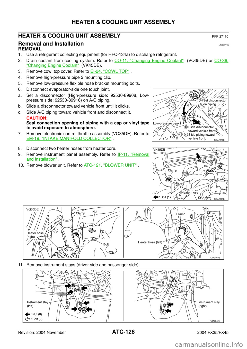
1. Use a refrigerant collecting equipment (for HFC-134a) to discharge refrigerant.
2. Drain coolant from cooling system. Refer to CO-11, "
Changing Engine Coolant" (VQ35DE) or CO-36,
"Changing Engine Coolant" (VK45DE).
3. Remove cowl top cover. Refer to EI-24, "
COWL TOP" .
4. Remove high-pressure pipe 2 mounting clip.
5. Remove low-pressure flexible hose bracket mounting bolts.
6. Disconnect evaporator-side one touch joint.
a. Set a disconnector (High-pressure side: 92530-89908, Low-
pressure side: 92530-89916) on A/C piping.
b. Slide a disconnector toward vehicle front until it clicks.
c. Slide A/C piping toward vehicle front and disconnect it.
CAUTION:
Seal connection opening of piping with a cap or vinyl tape
to avoid exposure to atmosphere.
7. Remove electronic control throttle assembly (VQ35DE). Refer to
EM-19, "
INTAKE MANIFOLD COLLECTOR" .
8. Disconnect two heater hoses from heater core.
9. Remove instrument panel assembly. Refer to IP-11, "
Removal
and Installation" .
10. Remove blower unit. Refer to ATC-121, "
BLOWER UNIT" .
11. Remove instrument stays (driver side and passenger side).
RJIA2037E
RJIA2041E
RJIA2077E
RJIA2042E
Page 649 of 4449

AV-58
INTEGRATED DISPLAY SYSTEM
Revision: 2004 November 2004 FX35/FX45
SETTING SCREEN
�Setting of electric status can be changed by A/C and AV switch. The signal is sent to BCM through display
unit to change vehicle electric system setting.
�Display unit is communicating with driver seat control unit.
�Pressing “SETTING” switch once cycles display from DISPLAY→LANGUAGE→BEEP SET→SERVICE
ALERT→PERSONALIZED SETTINGS MENU→DISPLAY OFF→DISPLAY.
�Using the joystick, setting of each item will become possible.
Adjustable Vehicle Status
NOTE:
Setting in factory shipment is ON.
Setting itemsSetting varia-
tionsInitial
settingOperation
DISPLAY ON/OFF ON It switches displayed/Non-displayed of the screen.
LANGUAGEENGLISH/
FRANCAIS– It switches displayed language.
BEEP SET ON/OFF ONIt selects beep sound ON/OFF during switch operation. How-
ever, even if beep is set OFF, beep for NO OPERATION and
for screen interception are not reset.
SERVICE ALERT ON/OFF OFFIt switches displayed/Non-displayed of alert indication.
�When the setting is ON, if engine oil or tire rotation will be
replace distance, alert is displayed.
�When the setting is OFF, alert is not displayed.
PERSONALIZED
SETTING MENUSLIDE BACK DR
SEAT ON EXITON/OFF
ON
NoteThe driver’s seat automatically moves back and returns to
the original position for exceptional ease of exit and entry.
(Models with automatic drive positioner.)
LIFT STEERING
WHEEL ON EXITON/OFF
ON
NoteThe steering column automatically tilts up and returns to the
original position for exceptional ease of entry and exit. (Mod-
els with automatic drive positioner.)
REMOTE UNLOCK
DOOR LOGICDR-1ST/ALL DR-1STThis key can switch the unlock doors of the 1st unlocking
operation as follows:
�Only the driver side door⇔All the doors
HORN CHIRP WITH
REMOTEON/OFF ONThis key changes the horn chirp mode occurring when press-
ing the LOCK button on the keyfob.
LAMPS FLASH
WITH REMOTEALL/LOCK/
UNLOCK/OFFALLThis key changes the hazard indicator flash mode occurring
when pressing the LOCK or UNLOCK button on the keyfob.
AUTO RE-LOCK
TIME5m/1m/OFF 1mThe length of auto door re-lock time can be set. Select the
“Auto Re-Lock timer” key, then move the joystick to adjust the
time.
AUTO HEADLAMP
SENSITIVITYLEVEL 1/2/3/4LEVEL
2Automatic light illumination can be set as desired. Select the
“Auto Headlamp Sensitivity” key, then move the joystick to
the left (lower) or right (higher).
AUTO HEADLAMP
OFF DELAYOFF/30/45/60/
90/120/150/
180 SEC45 SECThis key can control how long it takes the automatic turn off
timer to extinguish the headlamps in “AUTO” position. Select
the “Auto Headlamp Off Delay” key, then move the joystick to
the left or right to adjust the timer.
SPEED SENSING
WIPER INTERVALON/OFF ONThis key turns on and off the driving speed dependent inter-
mittent wiper function.
CONFIRM RESET
SETTINGSYES/NO NOWhen this key is selected and turned on using the “ENTER”
button, all settings mode by PERSONALIZED SETTINGS will
return to the initial conditions.