Page 451 of 4449

ATC-22
REFRIGERATION SYSTEM
Revision: 2004 November 2004 FX35/FX45
V-6 Variable Displacement CompressorAJS001BE
GENERAL INFORMATION
1. The V-6 variable compressor differs from previous units. The vent temperatures of the V-6 variable com-
pressor do not drop too far below 5°C (41°F) when:
Evaporator intake air temperature is less than 20°C (68°F).
Engine is running at speeds less than 1,500 rpm.
This is because the V-6 compressor provides a means of “capacity” control.
2. The V-6 variable compressor provides refrigerant control under varying conditions. During cold winters, it
may not produce high refrigerant pressure discharge (compared to previous units) when used with air
conditioning systems.
3. A “clanking” sound may occasionally be heard during refrigerant charge. The sound indicates that the tilt
angle of the wobble (swash) plate has changed and is not a malfunction.
4. For air conditioning systems with the V-6 compressor, the clutch remains engaged unless: the system
main switch, fan switch or ignition switch is turned OFF. When ambient (outside) temperatures are low or
when the amount of refrigerant is insufficient, the clutch is disengaged to protect the compressor.
Page 453 of 4449

ATC-24
REFRIGERATION SYSTEM
Revision: 2004 November 2004 FX35/FX45
Operation
1. Operation Control Valve
–By changing high-pressure valve lift amount, built-in compressor control valve executes the following:
Controls high-pressure valve discharge amount.
Changes crankcase pressure in compressor.
Changes angle of wobble (swash) plate.
–Amount of high-pressure valve loft is determined by factors below.
Low-pressure applied to diaphragm
Spring load of set spring
Balance of magnetic force generated in magnet coil
–Electronic control valve (ECV) magnet coil receives electric signal (duty control) from unified meter and A/
C amp. (Auto amp.) Then, magnetic force generated by electric current is changed to control high-pres-
sure valve lift amount.
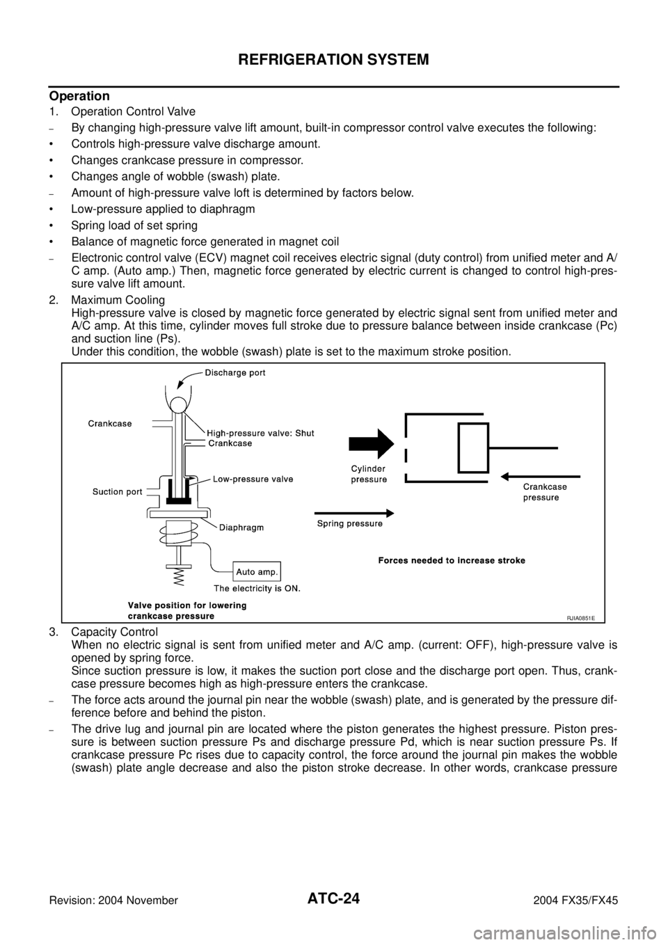
2. Maximum Cooling
High-pressure valve is closed by magnetic force generated by electric signal sent from unified meter and
A/C amp. At this time, cylinder moves full stroke due to pressure balance between inside crankcase (Pc)
and suction line (Ps).
Under this condition, the wobble (swash) plate is set to the maximum stroke position.
3. Capacity Control
When no electric signal is sent from unified meter and A/C amp. (current: OFF), high-pressure valve is
opened by spring force.
Since suction pressure is low, it makes the suction port close and the discharge port open. Thus, crank-
case pressure becomes high as high-pressure enters the crankcase.
–The force acts around the journal pin near the wobble (swash) plate, and is generated by the pressure dif-
ference before and behind the piston.
–The drive lug and journal pin are located where the piston generates the highest pressure. Piston pres-
sure is between suction pressure Ps and discharge pressure Pd, which is near suction pressure Ps. If
crankcase pressure Pc rises due to capacity control, the force around the journal pin makes the wobble
(swash) plate angle decrease and also the piston stroke decrease. In other words, crankcase pressure
RJIA0851E
Page 459 of 4449

ATC-30
AIR CONDITIONER CONTROL
Revision: 2004 November 2004 FX35/FX45
AIR CONDITIONER CONTROLPFP:27500
Description of Air Conditioner LAN Control SystemAJS0014A
The LAN (Local Area Network) system consists of unified meter and A/C amp., mode door motor, air mix door
motor and intake door motor.
A configuration of these components is shown in the diagram below.
System ConstructionAJS0014B
A small network is constructed between the unified meter and A/C amp., air mix door motor, mode door motor
and intake door motor. The unified meter and A/C amp. and motors are connected by data transmission lines
and motor power supply lines. The LAN network is built through the ground circuits of the each door motor.
Addresses, motor opening angle signals, motor stop signals and error checking messages are all transmitted
through the data transmission lines connecting the unified meter and A/C amp. and each door motor.
The following functions are contained in LCUs built into the air mix door motor, mode door motor and intake
door motor.
�Address
�Motor opening angle signals
�Data transmission
�Motor stop and drive decision
�Opening angle sensor (PBR function)
�Comparison
�Decision (Unified meter and A/C amp. indicated value and motor opening angle comparison)
OPERATION
The unified meter and A/C amp. receives data from each of the sensors. The unified meter and A/C amp.
sends mode door, air mix door and intake door opening angle data to the mode door motor LCU, air mix door
motor LCU and intake door motor LCU.
The mode door motor, air mix door motor and intake door motor read their respective signals according to the
address signal. Opening angle indication signals received from the unified meter and A/C amp. and each of
the motor position sensors are compared by the LCUs in each motor with the existing decision and opening
angles. Subsequently, HOT/COLD, DEFROST/VENT or FRESH/RECIRCULATION operation is selected. The
new selection data is returned to the unified meter and A/C amp.
SJIA0262E
RJIA1747E
Page 468 of 4449
AIR CONDITIONER CONTROL
ATC-39
C
D
E
F
G
H
I
K
L
MA
B
AT C
Revision: 2004 November 2004 FX35/FX45
CAN Communication System DescriptionAJS0014H
CAN (Controller Area Network) is a serial communication line for real time application. It is an on-vehicle mul-
tiplex communication line with high data communication speed and excellent error detection ability. Many elec-
tronic control units are equipped onto a vehicle, and each control unit shares information and links with other
control units during operation (not independent). In CAN communication, control units are connected with 2
communication lines (CAN H line, CAN L line) allowing a high rate of information transmission with less wiring.
Each control unit transmits/receives data but selectively reads required data only. For details, refer to LAN-6,
"CAN Communication Unit" .
Page 471 of 4449

ATC-42
TROUBLE DIAGNOSIS
Revision: 2004 November 2004 FX35/FX45
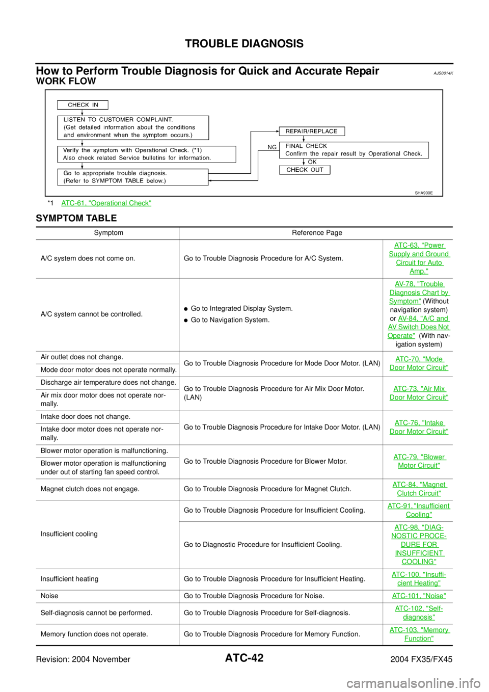
How to Perform Trouble Diagnosis for Quick and Accurate RepairAJS0014K
WORK FLOW
SYMPTOM TABLE
*1ATC-61, "Operational Check"
SHA900E
Symptom Reference Page
A/C system does not come on. Go to Trouble Diagnosis Procedure for A/C System.AT C - 6 3 , "
Power
Supply and Ground
Circuit for Auto
Amp."
A/C system cannot be controlled.�Go to Integrated Display System.
�Go to Navigation System.AV-78, "
Trouble
Diagnosis Chart by
Symptom" (Without
navigation system)
or AV-84, "
A/C and
AV Switch Does Not
Operate" (With nav-
igation system)
Air outlet does not change.
Go to Trouble Diagnosis Procedure for Mode Door Motor. (LAN)AT C - 7 0 , "
Mode
Door Motor Circuit"Mode door motor does not operate normally.
Discharge air temperature does not change.
Go to Trouble Diagnosis Procedure for Air Mix Door Motor.
(LAN)ATC-73, "
Air Mix
Door Motor Circuit"Air mix door motor does not operate nor-
mally.
Intake door does not change.
Go to Trouble Diagnosis Procedure for Intake Door Motor. (LAN)ATC-76, "
Intake
Door Motor Circuit"Intake door motor does not operate nor-
mally.
Blower motor operation is malfunctioning.
Go to Trouble Diagnosis Procedure for Blower Motor.ATC-79, "
Blower
Motor Circuit"Blower motor operation is malfunctioning
under out of starting fan speed control.
Magnet clutch does not engage. Go to Trouble Diagnosis Procedure for Magnet Clutch.ATC-84, "
Magnet
Clutch Circuit"
Insufficient coolingGo to Trouble Diagnosis Procedure for Insufficient Cooling.AT C - 9 1 , "
Insufficient
Cooling"
Go to Diagnostic Procedure for Insufficient Cooling.AT C - 9 8 , "
DIAG-
NOSTIC PROCE-
DURE FOR
INSUFFICIENT
COOLING"
Insufficient heating Go to Trouble Diagnosis Procedure for Insufficient Heating.ATC-100, "Insuffi-
cient Heating"
Noise Go to Trouble Diagnosis Procedure for Noise.ATC-101, "Noise"
Self-diagnosis cannot be performed. Go to Trouble Diagnosis Procedure for Self-diagnosis.ATC-102, "Self-
diagnosis"
Memory function does not operate. Go to Trouble Diagnosis Procedure for Memory Function.ATC-103, "Memory
Function"
Page 495 of 4449
ATC-66
TROUBLE DIAGNOSIS
Revision: 2004 November 2004 FX35/FX45
LAN System CircuitAJS0014S
SYMPTOM: Mode door motor, intake door motor and/or air mix door motor(s) does not operate normally.
DIAGNOSTIC PROCEDURE FOR LAN CIRCUIT
1. CHECK POWER SUPPLY FOR UNIFIED METER AND A/C AMP.
1. Turn ignition switch ON.
2. Check voltage between unified meter and A/C amp. harness
connector M57 terminal 54 (Y/R) and ground.
OK or NG
OK >> GO TO 2.
NG >> Replace unified meter and A/C amp.
2. CHECK SIGNAL FOR UNIFIED METER AND A/C AMP.
Confirm A/C LAN signal between unified meter and A/C amp. har-
ness connector M57 terminal 43 (G/B) and ground using an oscillo-
scope.
OK or NG
OK >> GO TO 3.
NG >> Replace unified meter and A/C amp.
RJIA1775E
54 – Ground : Battery voltage
RJIA1986E
Terminals
Voltage (+)
(−)
Unified meter and A/
C amp. connectorTerminal No.
(wire color)
M57 43 (G/B) Ground
RJIA1987E
HAK0652D
Page 500 of 4449

TROUBLE DIAGNOSIS
ATC-71
C
D
E
F
G
H
I
K
L
MA
B
AT C
Revision: 2004 November 2004 FX35/FX45
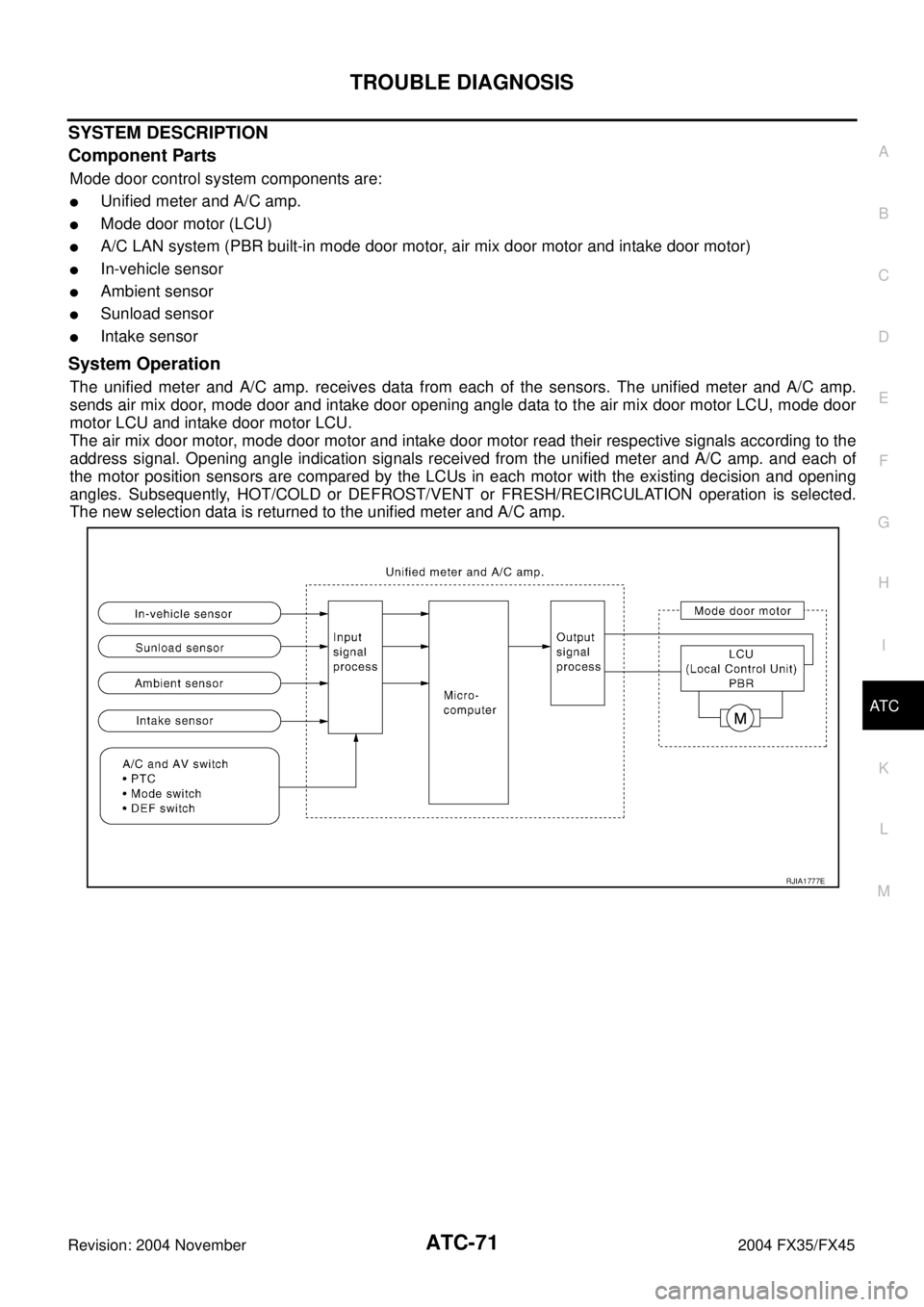
SYSTEM DESCRIPTION
Component Parts
Mode door control system components are:
�Unified meter and A/C amp.
�Mode door motor (LCU)
�A/C LAN system (PBR built-in mode door motor, air mix door motor and intake door motor)
�In-vehicle sensor
�Ambient sensor
�Sunload sensor
�Intake sensor
System Operation
The unified meter and A/C amp. receives data from each of the sensors. The unified meter and A/C amp.
sends air mix door, mode door and intake door opening angle data to the air mix door motor LCU, mode door
motor LCU and intake door motor LCU.
The air mix door motor, mode door motor and intake door motor read their respective signals according to the
address signal. Opening angle indication signals received from the unified meter and A/C amp. and each of
the motor position sensors are compared by the LCUs in each motor with the existing decision and opening
angles. Subsequently, HOT/COLD or DEFROST/VENT or FRESH/RECIRCULATION operation is selected.
The new selection data is returned to the unified meter and A/C amp.
RJIA1777E
Page 502 of 4449
TROUBLE DIAGNOSIS
ATC-73
C
D
E
F
G
H
I
K
L
MA
B
AT C
Revision: 2004 November 2004 FX35/FX45
Air Mix Door Motor CircuitAJS0014U
SYMPTOM:
�Discharge air temperature does not change.
�Air mix door motor does not operate.
INSPECTION FLOW
*1ATC-54, "FUNCTION CONFIRMA-
TION PROCEDURE", see No. 4 to 6.*2ATC-104, "
Ambient Sensor Circuit".*3ATC-107, "In-vehicle Sensor Cir-
cuit".
*4ATC-110, "
Sunload Sensor Circuit"*5ATC-73, "Air Mix Door Motor Cir-
cuit".*6ATC-54, "
FUNCTION CONFIRMA-
TION PROCEDURE", see No. 13.
*7ATC-66, "
LAN System Circuit".*8ATC-75, "COMPONENT DESCRIP-
TION".*9ATC-131, "
AIR MIX DOOR
MOTOR".
*10ATC-61, "
Operational Check".*11ATC-42, "SYMPTOM TABLE".*12ATC-113, "Intake Sensor Circuit".
RJIA1992E