Page 1012 of 4449

VEHICLE SECURITY (THEFT WARNING) SYSTEM
BL-205
C
D
E
F
G
H
J
K
L
MA
B
BL
Revision: 2004 November 2004 FX35/FX45
Diagnostic Procedure 3AIS004P6
FRONT DOOR KEY CYLINDER SWITCH CHECK
1. CHECK KEY CYLINDER SWITCH OPERATION
Check door key cylinder switch using key.
Do doors lock / unlock when using the key?
YES >> Front door key cylinder switch operation is OK.
NO >> Check door key cylinder switch circuit. Refer to GW-69, "
Front Door Key Cylinder Switch Check" .
Diagnostic Procedure 4AIS004P7
VEHICLE SECURITY HORN ALARM CHECK
1. CHECK HORN OPERATION
Check if horn sounds with horn switch.
Does horn operate?
YES >> Check harness for open or short between IPDM E/R and horn relay.
NO >> Check horn circuit. Refer to WW-56, "
HORN" .
Diagnostic Procedure 5AIS004P8
VEHICLE SECURITY HEADLAMP ALARM CHECK
1. CHECK HEADLAMP OPERATION
Check if headlamp operates by lighting switch.
Does headlamp come on when turning switch
“ON”?
YES >> Headlamp alarm circuit is OK.
NO >> Check headlamp system. Refer to LT- 7 , "
HEADLAMP - XENON TYPE -" or LT- 3 8 , "DAYTIME
LIGHT SYSTEM" .
Diagnostic Procedure 6AIS004P9
DOOR LOCK AND UNLOCK SWITCH CHECK
1. CHECK DOOR LOCK AND UNLOCK SWITCH INPUT SIGNAL
Check if power door lock operated by door lock and unlock switch.
Do doors lock / unlock when using each door lock and unlock switches?
YES >> Door lock and unlock switch is OK.
NO >> Check door lock and unlock switch. Refer to BL-48, "
Check Door Lock and Unlock Switch" .
Page 1019 of 4449
BL-212
IVIS (INFINITI VEHICLE IMMOBILIZER SYSTEM-NATS)
Revision: 2004 November 2004 FX35/FX45
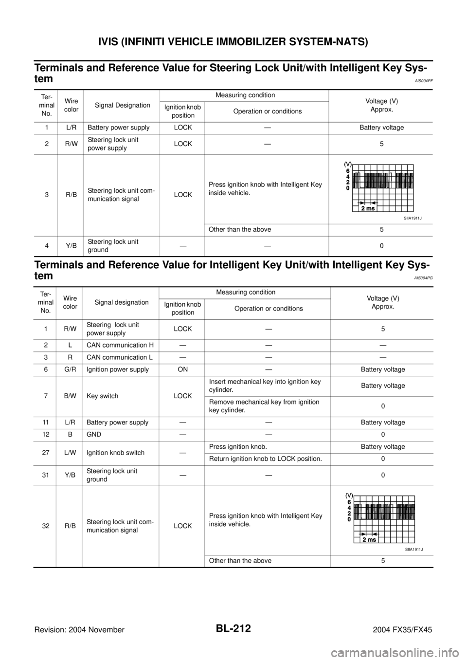
Terminals and Reference Value for Steering Lock Unit/with Intelligent Key Sys-
tem
AIS004PF
Terminals and Reference Value for Intelligent Key Unit/with Intelligent Key Sys-
tem
AIS004PG
Te r -
minal
No.Wire
colorSignal DesignationMeasuring condition
Voltage (V)
Approx. Ignition knob
positionOperation or conditions
1 L/R Battery power supply LOCK — Battery voltage
2R/WSteering lock unit
power supplyLOCK — 5
3R/BSteering lock unit com-
munication signalLOCKPress ignition knob with Intelligent Key
inside vehicle.
Other than the above 5
4Y/BSteering lock unit
ground—— 0
SIIA1911J
Te r -
minal
No.Wire
colorSignal designationMeasuring condition
Voltage (V)
Approx. Ignition knob
positionOperation or conditions
1R/WSteering lock unit
power supplyLOCK — 5
2 L CAN communication H — — —
3 R CAN communication L — — —
6 G/R Ignition power supply ON — Battery voltage
7 B/W Key switch LOCKInsert mechanical key into ignition key
cylinder.Battery voltage
Remove mechanical key from ignition
key cylinder.0
11 L/R Battery power supply — — Battery voltage
12 B GND — — 0
27 L/W Ignition knob switch —Press ignition knob. Battery voltage
Return ignition knob to LOCK position. 0
31 Y/BSteering lock unit
ground—— 0
32 R/BSteering lock unit com-
munication signalLOCKPress ignition knob with Intelligent Key
inside vehicle.
Other than the above 5
SIIA1911J
Page 1020 of 4449

IVIS (INFINITI VEHICLE IMMOBILIZER SYSTEM-NATS)
BL-213
C
D
E
F
G
H
J
K
L
MA
B
BL
Revision: 2004 November 2004 FX35/FX45
Terminals and Reference Value for BCMAIS004PH
*: With Intelligent Key systemTe r -
minal
No.Wire
colorSignal designationMeasuring condition
Voltage (V)
Approx. Ignition knob
positionOperation or conditions
21 G/B NATS antenna apm. — Ignition knob OFF → ON positionTester pointer should move just
after turning ignition knob “ON”
23 G/OR Security indicator lamp LOCKGoes OFF → illuminates (Every 2.4
seconds)Battery voltage → 0
25 BR NATS antenna amp. — Ignition knob OFF → ON positionTester pointer should move just
after turning ignition knob “ON”
37* B/W Key switch —Insert mechanical key into ignition key
cylinderBattery voltage
Remove mechanical key from ignition
key cylinder0
38 W/L Ignition power supply ON Ignition knob ON or START position Battery voltage
39 L CAN-H — — —
40 R CAN-L — — —
42 L/R Battery power supply — — Battery voltage
49 B GND — — 0
52 B GND — — 0
55 G Battery power supply — — Battery voltage
Page 1027 of 4449
BL-220
IVIS (INFINITI VEHICLE IMMOBILIZER SYSTEM-NATS)
Revision: 2004 November 2004 FX35/FX45
Diagnostic Procedure 2AIS004PN
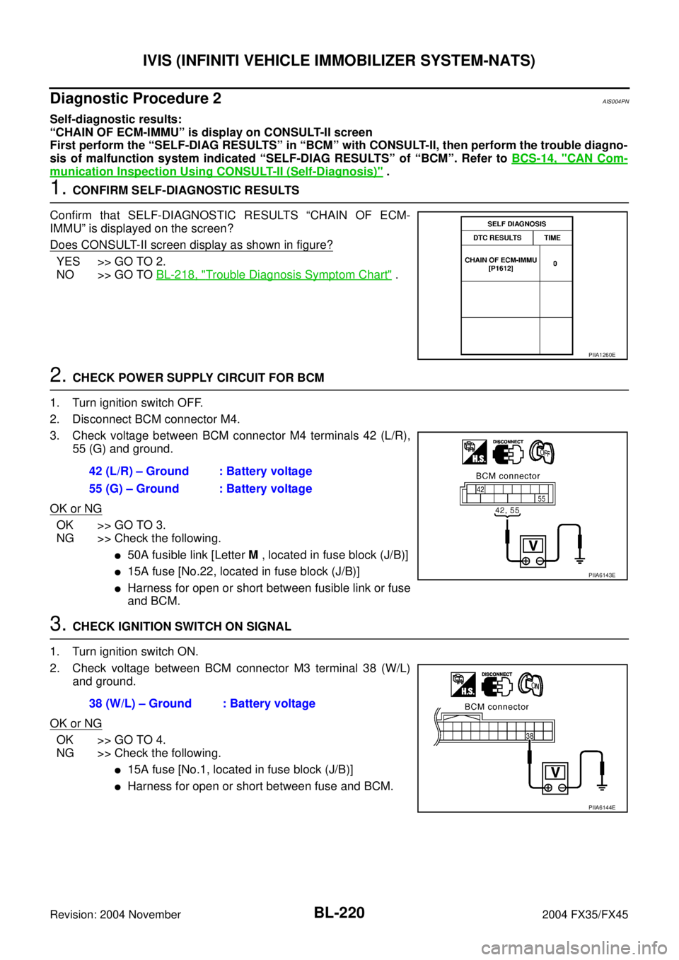
Self-diagnostic results:
“CHAIN OF ECM-IMMU” is display on CONSULT-II screen
First perform the “SELF-DIAG RESULTS” in “BCM” with CONSULT-II, then perform the trouble diagno-
sis of malfunction system indicated “SELF-DIAG RESULTS” of “BCM”. Refer to BCS-14, "
CAN Com-
munication Inspection Using CONSULT-II (Self-Diagnosis)" .
1. CONFIRM SELF-DIAGNOSTIC RESULTS
Confirm that SELF-DIAGNOSTIC RESULTS “CHAIN OF ECM-
IMMU” is displayed on the screen?
Does CONSULT-II screen display as shown in figure?
YES >> GO TO 2.
NO >> GO TO BL-218, "
Trouble Diagnosis Symptom Chart" .
2. CHECK POWER SUPPLY CIRCUIT FOR BCM
1. Turn ignition switch OFF.
2. Disconnect BCM connector M4.
3. Check voltage between BCM connector M4 terminals 42 (L/R),
55 (G) and ground.
OK or NG
OK >> GO TO 3.
NG >> Check the following.
�50A fusible link [Letter M , located in fuse block (J/B)]
�15A fuse [No.22, located in fuse block (J/B)]
�Harness for open or short between fusible link or fuse
and BCM.
3. CHECK IGNITION SWITCH ON SIGNAL
1. Turn ignition switch ON.
2. Check voltage between BCM connector M3 terminal 38 (W/L)
and ground.
OK or NG
OK >> GO TO 4.
NG >> Check the following.
�15A fuse [No.1, located in fuse block (J/B)]
�Harness for open or short between fuse and BCM.
PIIA1260E
42 (L/R) – Ground : Battery voltage
55 (G) – Ground : Battery voltage
PIIA6143E
38 (W/L) – Ground : Battery voltage
PIIA6144E
Page 1032 of 4449
IVIS (INFINITI VEHICLE IMMOBILIZER SYSTEM-NATS)
BL-225
C
D
E
F
G
H
J
K
L
MA
B
BL
Revision: 2004 November 2004 FX35/FX45
4. CHECK POWER SUPPLY FOR NATS ANTENNA AMP.
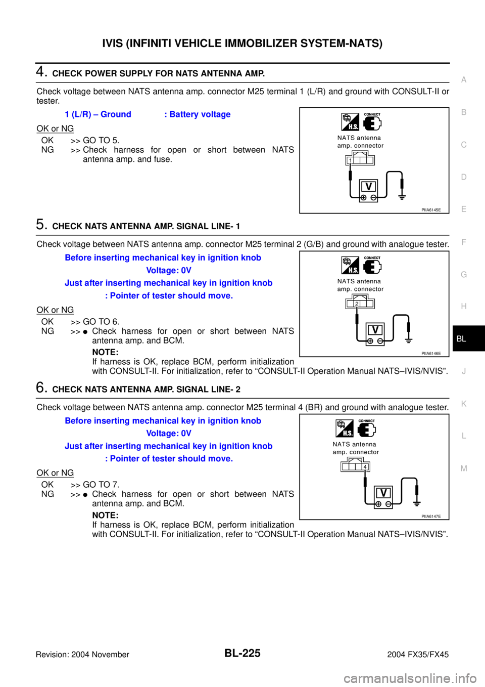
Check voltage between NATS antenna amp. connector M25 terminal 1 (L/R) and ground with CONSULT-II or
tester.
OK or NG
OK >> GO TO 5.
NG >> Check harness for open or short between NATS
antenna amp. and fuse.
5. CHECK NATS ANTENNA AMP. SIGNAL LINE- 1
Check voltage between NATS antenna amp. connector M25 terminal 2 (G/B) and ground with analogue tester.
OK or NG
OK >> GO TO 6.
NG >>
�Check harness for open or short between NATS
antenna amp. and BCM.
NOTE:
If harness is OK, replace BCM, perform initialization
with CONSULT-II. For initialization, refer to “CONSULT-II Operation Manual NATS–IVIS/NVIS”.
6. CHECK NATS ANTENNA AMP. SIGNAL LINE- 2
Check voltage between NATS antenna amp. connector M25 terminal 4 (BR) and ground with analogue tester.
OK or NG
OK >> GO TO 7.
NG >>
�Check harness for open or short between NATS
antenna amp. and BCM.
NOTE:
If harness is OK, replace BCM, perform initialization
with CONSULT-II. For initialization, refer to “CONSULT-II Operation Manual NATS–IVIS/NVIS”. 1 (L/R) – Ground : Battery voltage
PIIA6145E
Before inserting mechanical key in ignition knob
Voltage: 0V
Just after inserting mechanical key in ignition knob
: Pointer of tester should move.
PIIA6146E
Before inserting mechanical key in ignition knob
Voltage: 0V
Just after inserting mechanical key in ignition knob
: Pointer of tester should move.
PIIA6147E
Page 1033 of 4449
BL-226
IVIS (INFINITI VEHICLE IMMOBILIZER SYSTEM-NATS)
Revision: 2004 November 2004 FX35/FX45
7. CHECK NATS ANTENNA AMP. GROUND LINE CIRCUIT
1. Turn ignition switch “OFF”.
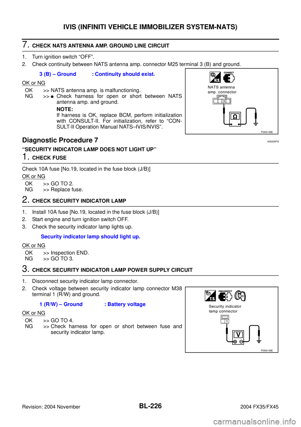
2. Check continuity between NATS antenna amp. connector M25 terminal 3 (B) and ground.
OK or NG
OK >> NATS antenna amp. is malfunctioning.
NG >>
�Check harness for open or short between NATS
antenna amp. and ground.
NOTE:
If harness is OK, replace BCM, perform initialization
with CONSULT-II. For initialization, refer to “CON-
SULT-II Operation Manual NATS–IVIS/NVIS”.
Diagnostic Procedure 7AIS004PS
“SECURITY INDICATOR LAMP DOES NOT LIGHT UP”
1. CHECK FUSE
Check 10A fuse [No.19, located in the fuse block (J/B)]
OK or NG
OK >> GO TO 2.
NG >> Replace fuse.
2. CHECK SECURITY INDICATOR LAMP
1. Install 10A fuse [No.19, located in the fuse block (J/B)]
2. Start engine and turn ignition switch OFF.
3. Check the security indicator lamp lights up.
OK or NG
OK >> Inspection END.
NG >> GO TO 3.
3. CHECK SECURITY INDICATOR LAMP POWER SUPPLY CIRCUIT
1. Disconnect security indicator lamp connector.
2. Check voltage between security indicator lamp connector M38
terminal 1 (R/W) and ground.
OK or NG
OK >> GO TO 4.
NG >> Check harness for open or short between fuse and
security indicator lamp. 3 (B) – Ground : Continuity should exist.
PIIA6148E
Security indicator lamp should light up.
1 (R/W) – Ground : Battery voltage
PIIA6149E
Page 1036 of 4449
INTEGRATED HOMELINK TRANSMITTER
BL-229
C
D
E
F
G
H
J
K
L
MA
B
BL
Revision: 2004 November 2004 FX35/FX45
Trouble DiagnosesAIS004PV
DIAGNOSTIC PROCEDURE
SYMPTOM: Transmitter Does Not Activate Receiver.
Before conducting the procedure given below, make sure that system receiver (garage door opener, etc.)
operates with original, hand-held transmitter. If NG, receiver or hand-held transmitter is malfunctioning, not
vehicle related.
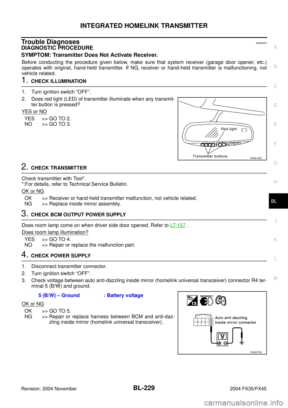
1. CHECK ILLUMINATION
1. Turn ignition switch “OFF”.
2. Does red light (LED) of transmitter illuminate when any transmit-
ter button is pressed?
YES or NO
YES >> GO TO 2.
NO >> GO TO 3.
2. CHECK TRANSMITTER
Check transmitter with Tool*.
*:For details, refer to Technical Service Bulletin.
OK or NG
OK >> Receiver or hand-held transmitter malfunction, not vehicle related.
NG >> Replace inside mirror assembly.
3. CHECK BCM OUTPUT POWER SUPPLY
Does room lamp come on when driver side door opened. Refer to LT- 1 5 7
.
Does room lamp illumination?
YES >> GO TO 4.
NO >> Repair or replace the malfunction part.
4. CHECK POWER SUPPLY
1. Disconnect transmitter connector.
2. Turn ignition switch “OFF”.
3. Check voltage between auto anti-dazzling inside mirror (homelink universal transceiver) connector R4 ter-
minal 5 (B/W) and ground.
OK or NG
OK >> GO TO 5.
NG >> Repair or replace harness between BCM and anti-daz-
zling inside mirror (homelink universal transceiver).
PIIA6142E
5 (B/W) – Ground : Battery voltage
PIIA2370E
Page 1097 of 4449
BR-4
PREPARATION
Revision: 2004 November 2004 FX35/FX45
PREPARATIONPFP:00002
Commercial Service ToolsAFS001MR
Tool nameDescription
1. Flare nut crowfoot
a:10 mm (0.39 in) / 12 mm (0.47 in)
2. Torque wrenchRemoving and installing each brake
piping
Power toolRemoving front and rear caliper
assembly, tires
S-NT360
PBIC0190E
PBIC0191E