Page 496 of 4449
,")
TROUBLE DIAGNOSIS
ATC-67
C
D
E
F
G
H
I
K
L
MA
B
AT C
Revision: 2004 November 2004 FX35/FX45
3. CHECK POWER SUPPLY FOR MOTOR
Check voltage between mode door motor harness connector M258
terminal 1 (G), driver side air mix door motor harness connector
M252 terminal 1 (G), passenger side air mix door motor harness
connector M257 terminal 1 (G), intake door motor harness connector
M253 terminal 1 (G) and ground.
OK or NG
OK >> GO TO 4.
NG >> Repair harness or connector.
4. CHECK SIGNAL FOR MOTOR
Confirm A/C LAN signal between mode door motor harness connec-
tor M258 terminal 3 (L), driver side air mix door motor harness con-
nector M252 terminal 3 (L), passenger side air mix door motor
harness connector M257 terminal 3 (L), intake door motor harness
connector M253 terminal 3 (G/B) and ground using an oscilloscope.
OK or NG
OK >> GO TO 5.
NG >> Repair harness or connector.
5. CHECK MOTOR GROUND CIRCUIT
1. Turn ignition switch OFF.
2. Disconnect door motor connector.
3. Check continuity between mode door motor harness connector
M258 terminal 2 (B), driver side air mix door motor harness con-
nector M252 terminal 2 (B), passenger side air mix door motor
harness connector M257 terminal 2 (B), intake door motor har-
ness connector M253 terminal 2 (B) and ground.
OK or NG
OK >> GO TO 6.
NG >> Repair harness or connector.1 – Ground : Battery voltage
RJIA1988E
Door motorTerminals
Voltage (+)
(−)
Con-
nectorTerminal
No.
(wire color)
Mode M258 3 (L)
Ground Air mix
(Driver
side)M252 3 (L)
Air mix
(Passen-
ger side)M257 3 (L)
Intake M253 3 (L)
RJIA1989E
HAK0652D
2 – Ground : Continuity should exist.
RJIA1990E
Page 497 of 4449

ATC-68
TROUBLE DIAGNOSIS
Revision: 2004 November 2004 FX35/FX45
6. CHECK MOTOR OPERATION
1. Turn ignition switch OFF.
2. Disconnect each door motor connector.
3. Reconnect each door motor connector.
4. Turn ignition switch ON.
5. Confirm each door motor operation.
OK or NG
OK >> (Return to operate normally.)
�Poor contact in motor connector.
NG >> (Does not operate normally.)
�GO TO 7.
7. CHECK MODE DOOR MOTOR OPERATION
1. Turn ignition switch OFF.
2. Disconnect mode door motor and air mix door motor (driver side, passenger side) connector.
3. Reconnect mode door motor connector.
4. Turn ignition switch ON.
5. Confirm the mode door motor operation.
OK or NG
OK >> (Mode door motor operates normally.)
�GO TO 8.
NG >> (Mode door motor does not operate normally.)
�Repair mode door motor.
8. CHECK AIR MIX DOOR MOTOR OPERATION
1. Turn ignition switch OFF.
2. Disconnect mode door motor connector.
3. Reconnect air mix door motor connector (driver side, passenger side).
4. Turn ignition switch ON.
5. Confirm the air mix door motor operation.
OK or NG
OK >> (Air mix door motor operates normally.)
�GO TO 9.
NG >> (Air mix door motor does not operate normally.)
�GO TO 10.
9. CHECK INTAKE DOOR MOTOR OPERATION
1. Turn ignition switch OFF.
2. Disconnect air mix door motor connector (driver side, passenger side).
3. Reconnect intake door motor connector.
4. Turn ignition switch ON.
5. Confirm the intake door motor operation.
OK or NG
OK >> (Intake door motor operates normally.)
�Repair unified meter and A/C amp.
NG >> (Intake door motor does not operate normally.)
�Repair intake door motor.
Page 499 of 4449
ATC-70
TROUBLE DIAGNOSIS
Revision: 2004 November 2004 FX35/FX45
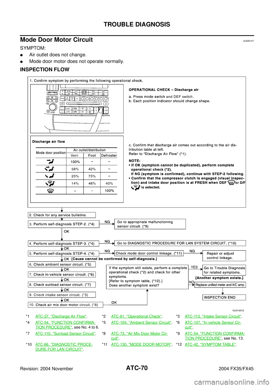
Mode Door Motor CircuitAJS0014T
SYMPTOM:
�Air outlet does not change.
�Mode door motor does not operate normally.
INSPECTION FLOW
*1AT C - 3 7 , "Discharge Air Flow".*2ATC-61, "Operational Check".*3ATC-113, "Intake Sensor Circuit".
*4AT C - 5 4 , "
FUNCTION CONFIRMA-
TION PROCEDURE", see No. 4 to 6.*5ATC-104, "
Ambient Sensor Circuit".*6ATC-107, "In-vehicle Sensor Cir-
cuit".
*7AT C - 11 0 , "
Sunload Sensor Circuit".*8ATC-73, "Air Mix Door Motor Cir-
cuit".*9ATC-54, "
FUNCTION CONFIRMA-
TION PROCEDURE", see No. 13.
*10AT C - 6 6 , "
DIAGNOSTIC PROCE-
DURE FOR LAN CIRCUIT".*11ATC-130, "
MODE DOOR MOTOR".*12ATC-42, "SYMPTOM TABLE".
RJIA1991E
Page 500 of 4449

TROUBLE DIAGNOSIS
ATC-71
C
D
E
F
G
H
I
K
L
MA
B
AT C
Revision: 2004 November 2004 FX35/FX45
SYSTEM DESCRIPTION
Component Parts
Mode door control system components are:
�Unified meter and A/C amp.
�Mode door motor (LCU)
�A/C LAN system (PBR built-in mode door motor, air mix door motor and intake door motor)
�In-vehicle sensor
�Ambient sensor
�Sunload sensor
�Intake sensor
System Operation
The unified meter and A/C amp. receives data from each of the sensors. The unified meter and A/C amp.
sends air mix door, mode door and intake door opening angle data to the air mix door motor LCU, mode door
motor LCU and intake door motor LCU.
The air mix door motor, mode door motor and intake door motor read their respective signals according to the
address signal. Opening angle indication signals received from the unified meter and A/C amp. and each of
the motor position sensors are compared by the LCUs in each motor with the existing decision and opening
angles. Subsequently, HOT/COLD or DEFROST/VENT or FRESH/RECIRCULATION operation is selected.
The new selection data is returned to the unified meter and A/C amp.
RJIA1777E
Page 502 of 4449
TROUBLE DIAGNOSIS
ATC-73
C
D
E
F
G
H
I
K
L
MA
B
AT C
Revision: 2004 November 2004 FX35/FX45
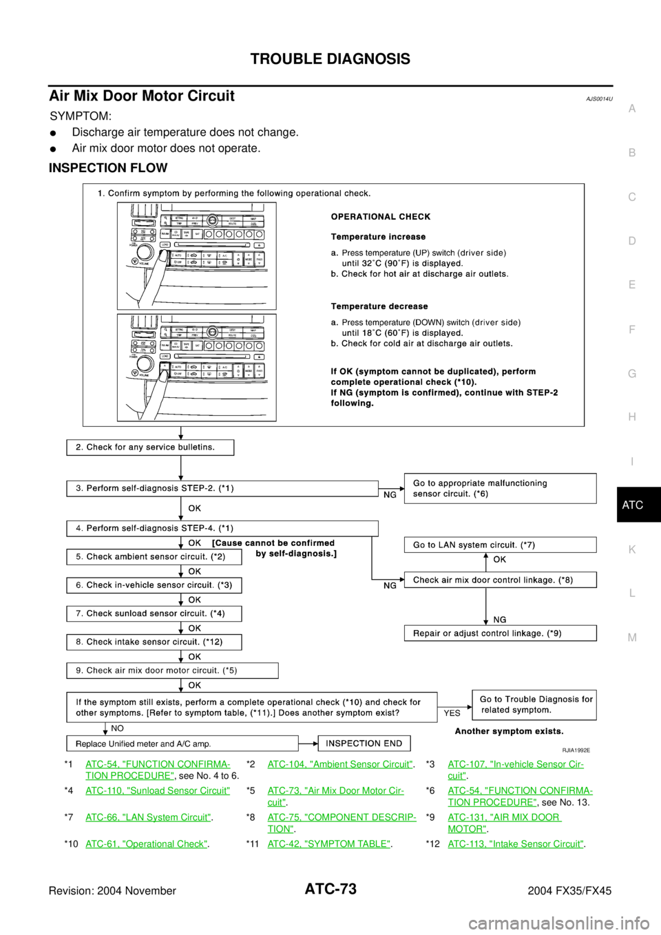
Air Mix Door Motor CircuitAJS0014U
SYMPTOM:
�Discharge air temperature does not change.
�Air mix door motor does not operate.
INSPECTION FLOW
*1ATC-54, "FUNCTION CONFIRMA-
TION PROCEDURE", see No. 4 to 6.*2ATC-104, "
Ambient Sensor Circuit".*3ATC-107, "In-vehicle Sensor Cir-
cuit".
*4ATC-110, "
Sunload Sensor Circuit"*5ATC-73, "Air Mix Door Motor Cir-
cuit".*6ATC-54, "
FUNCTION CONFIRMA-
TION PROCEDURE", see No. 13.
*7ATC-66, "
LAN System Circuit".*8ATC-75, "COMPONENT DESCRIP-
TION".*9ATC-131, "
AIR MIX DOOR
MOTOR".
*10ATC-61, "
Operational Check".*11ATC-42, "SYMPTOM TABLE".*12ATC-113, "Intake Sensor Circuit".
RJIA1992E
Page 503 of 4449

�A/")
ATC-74
TROUBLE DIAGNOSIS
Revision: 2004 November 2004 FX35/FX45
SYSTEM DESCRIPTION
Component Parts
Air mix door control system components are:
�Unified meter and A/C amp.
�Air mix door motor (LCU)
�A/C LAN system (PBR built-in mode door motor, air mix door motor and intake door motor)
�In-vehicle sensor
�Ambient sensor
�Sunload sensor
�Intake sensor
System Operation
The unified meter and A/C amp. receives data from each of the sensors. The unified meter and A/C amp.
sends air mix door, mode door and intake door opening angle data to the air mix door motor LCU, mode door
motor LCU and intake door motor LCU.
The air mix door motor, mode door motor and intake door motor read their respective signals according to the
address signal. Opening angle indication signals received from the unified meter and A/C amp. and each of
the motor position sensors are compared by the LCUs in each motor with the existing decision and opening
angles. Subsequently, HOT/COLD or DEFROST/VENT or FRESH/RECIRCULATION operation is selected.
The new selection data is returned to the unified meter and A/C amp.
Air Mix Door Control Specification
RJIA1781E
RJIA1782E
Page 505 of 4449
ATC-76
TROUBLE DIAGNOSIS
Revision: 2004 November 2004 FX35/FX45
Intake Door Motor CircuitAJS0014W
SYMPTOM:
�Intake door does not change.
�Intake door motor does not operate normally.
INSPECTION FLOW
*1AT C - 5 4 , "FUNCTION CONFIRMA-
TION PROCEDURE", see No. 4 to 6.*2ATC-104, "
Ambient Sensor Circuit".*3ATC-107, "In-vehicle Sensor Circuit".
*4AT C - 11 0 , "
Sunload Sensor Circuit".*5AT C - 7 3 , "Air Mix Door Motor Cir-
cuit".*6AT C - 5 4 , "
FUNCTION CONFIRMA-
TION PROCEDURE", see No. 13.
*7AT C - 6 6 , "
LAN System Circuit".*8ATC-124, "INTAKE DOOR
MOTOR".*9AT C - 6 1 , "
Operational Check".
*10AT C - 4 2 , "
SYMPTOM TABLE".*11AT C - 11 3 , "Intake Sensor Circuit".
RJIA1993E
Page 506 of 4449
TROUBLE DIAGNOSIS
ATC-77
C
D
E
F
G
H
I
K
L
MA
B
AT C
Revision: 2004 November 2004 FX35/FX45
SYSTEM DESCRIPTION
Component Parts
Intake door control system components are:
�Unified meter and A/C amp.
�Intake door motor (LCU)
�A/C LAN system (PBR built-in mode door motor, air mix door motor and intake door motor)
�In-vehicle sensor
�Ambient sensor
�Sunload sensor
�Intake sensor
System Operation
The intake door control determines intake door position based on the ambient temperature, the intake air tem-
perature and the in-vehicle temperature. When the DEFROST, or OFF switches are pushed or A/C switch is
OFF, the unified meter and A/C amp. sets the intake door at the FRESH position.
Intake Door Control Specification
RJIA1786E
RJIA1787E