Page 493 of 4449

ATC-64
TROUBLE DIAGNOSIS
Revision: 2004 November 2004 FX35/FX45
COMPONENT DESCRIPTION
Unified Meter and A/C amp. (Automatic Amplifier)
The unified meter and A/C amp. has a built-in microcomputer which
processes information sent from various sensors needed for air con-
ditioner operation. The air mix door motor, mode door motor, intake
door motor, blower motor and compressor are then controlled.
The unified meter and A/C amp. is unitized with control mechanisms.
When the various switches and temperature switch are operated,
data is input to the unified meter and A/C amp. from the DISPLAY
UNIT/DISPLAY C/U using CAN communication.
Self-diagnostic functions are also built into unified meter and A/C
amp. to provide quick check of malfunctions in the auto air condi-
tioner system.
Potentio Temperature Control (PTC)
The PTC is built into the A/C and AV switch. It can be set at an inter-
val of 0.5°C (1.0°F) in the 18°C (60°F) to 32°C (90°F) temperature
range by pressing temperature switch. The set temperature is dis-
played.
DIAGNOSTIC PROCEDURE FOR A/C SYSTEM
SYMPTOM: A/C system does not come on.
RJIA1965E
RJIA1982E
RJIA1983E
Page 500 of 4449

TROUBLE DIAGNOSIS
ATC-71
C
D
E
F
G
H
I
K
L
MA
B
AT C
Revision: 2004 November 2004 FX35/FX45
SYSTEM DESCRIPTION
Component Parts
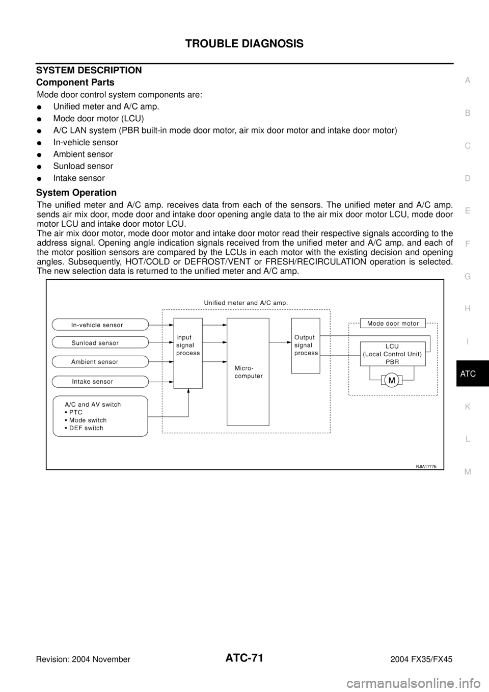
Mode door control system components are:
�Unified meter and A/C amp.
�Mode door motor (LCU)
�A/C LAN system (PBR built-in mode door motor, air mix door motor and intake door motor)
�In-vehicle sensor
�Ambient sensor
�Sunload sensor
�Intake sensor
System Operation
The unified meter and A/C amp. receives data from each of the sensors. The unified meter and A/C amp.
sends air mix door, mode door and intake door opening angle data to the air mix door motor LCU, mode door
motor LCU and intake door motor LCU.
The air mix door motor, mode door motor and intake door motor read their respective signals according to the
address signal. Opening angle indication signals received from the unified meter and A/C amp. and each of
the motor position sensors are compared by the LCUs in each motor with the existing decision and opening
angles. Subsequently, HOT/COLD or DEFROST/VENT or FRESH/RECIRCULATION operation is selected.
The new selection data is returned to the unified meter and A/C amp.
RJIA1777E
Page 501 of 4449
ATC-72
TROUBLE DIAGNOSIS
Revision: 2004 November 2004 FX35/FX45
Mode Door Control Specification
COMPONENT DESCRIPTION
Mode Door Motor
The mode door motor is attached to the heater & cooling unit. It
rotates so that air is discharged from the outlet set by the unified
meter and A/C amp. Motor rotation is conveyed to a link which acti-
vates the mode door.
DIAGNOSTIC PROCEDURE FOR MODE DOOR MOTOR
SYMPTOM: Mode door motor does not operate normally.
Perform diagnostic procedure for AT C - 6 6 , "
DIAGNOSTIC PROCEDURE FOR LAN CIRCUIT" .
RJIA1778E
RJIA0890E
Page 503 of 4449

ATC-74
TROUBLE DIAGNOSIS
Revision: 2004 November 2004 FX35/FX45
SYSTEM DESCRIPTION
Component Parts
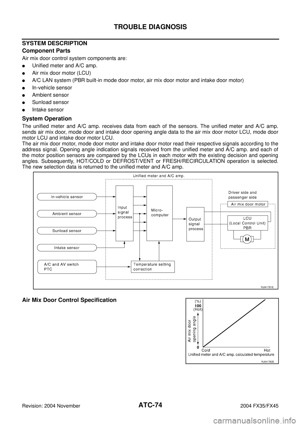
Air mix door control system components are:
�Unified meter and A/C amp.
�Air mix door motor (LCU)
�A/C LAN system (PBR built-in mode door motor, air mix door motor and intake door motor)
�In-vehicle sensor
�Ambient sensor
�Sunload sensor
�Intake sensor
System Operation
The unified meter and A/C amp. receives data from each of the sensors. The unified meter and A/C amp.
sends air mix door, mode door and intake door opening angle data to the air mix door motor LCU, mode door
motor LCU and intake door motor LCU.
The air mix door motor, mode door motor and intake door motor read their respective signals according to the
address signal. Opening angle indication signals received from the unified meter and A/C amp. and each of
the motor position sensors are compared by the LCUs in each motor with the existing decision and opening
angles. Subsequently, HOT/COLD or DEFROST/VENT or FRESH/RECIRCULATION operation is selected.
The new selection data is returned to the unified meter and A/C amp.
Air Mix Door Control Specification
RJIA1781E
RJIA1782E
Page 506 of 4449
TROUBLE DIAGNOSIS
ATC-77
C
D
E
F
G
H
I
K
L
MA
B
AT C
Revision: 2004 November 2004 FX35/FX45
SYSTEM DESCRIPTION
Component Parts
Intake door control system components are:
�Unified meter and A/C amp.
�Intake door motor (LCU)
�A/C LAN system (PBR built-in mode door motor, air mix door motor and intake door motor)
�In-vehicle sensor
�Ambient sensor
�Sunload sensor
�Intake sensor
System Operation
The intake door control determines intake door position based on the ambient temperature, the intake air tem-
perature and the in-vehicle temperature. When the DEFROST, or OFF switches are pushed or A/C switch is
OFF, the unified meter and A/C amp. sets the intake door at the FRESH position.
Intake Door Control Specification
RJIA1786E
RJIA1787E
Page 508 of 4449
TROUBLE DIAGNOSIS
ATC-79
C
D
E
F
G
H
I
K
L
MA
B
AT C
Revision: 2004 November 2004 FX35/FX45
Blower Motor CircuitAJS0014X
SYMPTOM:
�Blower motor operation is malfunctioning.
�Blower motor operation is malfunctioning under out of starting fan speed control.
INSPECTION FLOW
*1ATC-61, "Operational Check".*2AT C - 11 3 , "Intake Sensor Circuit".*3ATC-54, "FUNCTION CONFIRMA-
TION PROCEDURE", see No.4.
*4ATC-54, "
FUNCTION CONFIRMA-
TION PROCEDURE", see No.6.*5AT C - 5 4 , "
FUNCTION CONFIRMA-
TION PROCEDURE", see No.13.*6ATC-81, "
DIAGNOSTIC PROCE-
DURE FOR BLOWER MOTOR".
RJIA1994E
Page 509 of 4449

ATC-80
TROUBLE DIAGNOSIS
Revision: 2004 November 2004 FX35/FX45
SYSTEM DESCRIPTION
Component Parts
Fan speed control system components are:
�Unified meter and A/C amp.
�A/C LAN system (PBR built-in mode door motor, air mix door motor and intake door motor)
�In-vehicle sensor
�Ambient sensor
�Sunload sensor
�Intake sensor
System Operation
Automatic Mode
In the automatic mode, the blower motor speed is calculated by the unified meter and A/C amp. based on
input from the PBR, in-vehicle sensor, sunload sensor, intake sensor and ambient sensor.
When the air flow is increased, the duty ratio of the blower fan motor′s drive signal is changed at 8%/sec. to
prevent a sudden increase in air flow.
In addition to manual air flow control and the usual automatic air flow control, starting air flow control, low
water temperature starting control and high passenger compartment temperature starting control are avail-
able.
*7AT C - 4 2 , "SYMPTOM TABLE".*8ATC-104, "Ambient Sensor Circuit".*9ATC-107, "In-vehicle Sensor Cir-
cuit".
*10AT C - 11 0 , "
Sunload Sensor Circuit".*11EC-185, "DTC P0117, P0118 ECT
SENSOR" (VQ35DE) or EC-842,
"DTC P0117, P0118 ECT SEN-
SOR" (VK45DE).
RJIA1995E
Page 510 of 4449

TROUBLE DIAGNOSIS
ATC-81
C
D
E
F
G
H
I
K
L
MA
B
AT C
Revision: 2004 November 2004 FX35/FX45
Starting Fan Speed Control
Start Up from COLD SOAK Condition (Automatic mode)
In a cold start up condition where the engine coolant temperature is below 56°C (133°F), the blower will not
operate for a short period of time (up to 150 seconds). The exact start delay time varies depending on the
ambient and engine coolant temperature.
In the most extreme case (very low ambient) the blower starting delay will be 150 seconds as described
above. After this delay, the blower will operate at low speed until the engine coolant temperature rises above
56°C (133°F), at which time the blower speed will increase to the objective speed.
Start Up from Usual or HOT SOAK Condition (Automatic mode)
The blower will begin operation momentarily after the AUTO switch is pushed. The blower speed will gradually
rise to the objective speed over a time period of 3 seconds or less (actual time depends on the objective
blower speed).
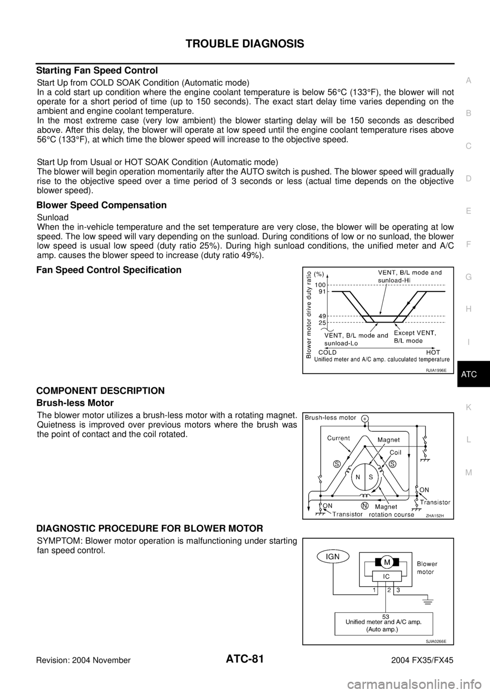
Blower Speed Compensation
Sunload
When the in-vehicle temperature and the set temperature are very close, the blower will be operating at low
speed. The low speed will vary depending on the sunload. During conditions of low or no sunload, the blower
low speed is usual low speed (duty ratio 25%). During high sunload conditions, the unified meter and A/C
amp. causes the blower speed to increase (duty ratio 49%).
Fan Speed Control Specification
COMPONENT DESCRIPTION
Brush-less Motor
The blower motor utilizes a brush-less motor with a rotating magnet.
Quietness is improved over previous motors where the brush was
the point of contact and the coil rotated.
DIAGNOSTIC PROCEDURE FOR BLOWER MOTOR
SYMPTOM: Blower motor operation is malfunctioning under starting
fan speed control.
RJIA1996E
ZHA152H
SJIA0266E