Page 694 of 4449
NAVIGATION SYSTEM
AV-103
C
D
E
F
G
H
I
J
L
MA
B
AV
Revision: 2004 November 2004 FX35/FX45
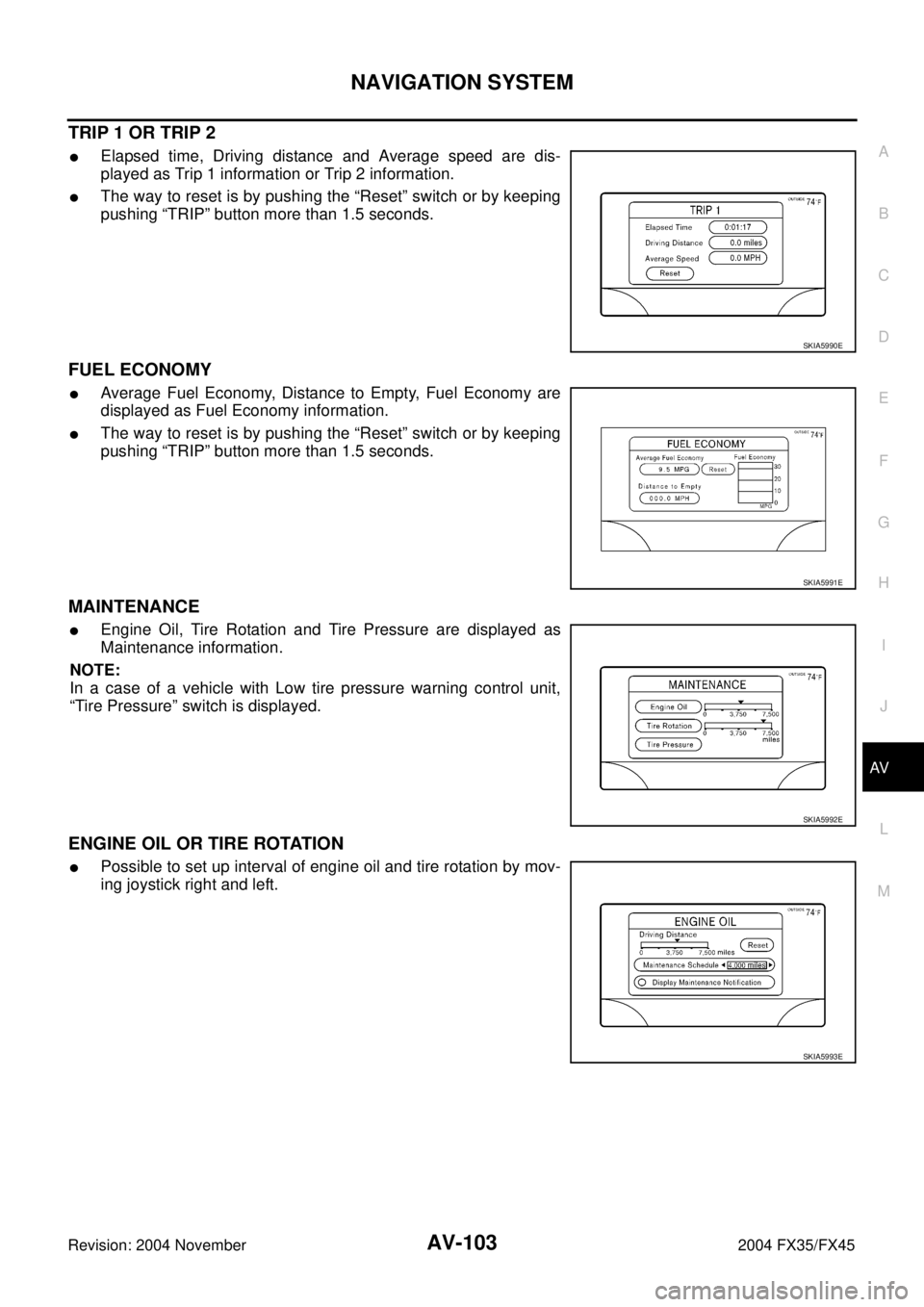
TRIP 1 OR TRIP 2
�Elapsed time, Driving distance and Average speed are dis-
played as Trip 1 information or Trip 2 information.
�The way to reset is by pushing the “Reset” switch or by keeping
pushing “TRIP” button more than 1.5 seconds.
FUEL ECONOMY
�Average Fuel Economy, Distance to Empty, Fuel Economy are
displayed as Fuel Economy information.
�The way to reset is by pushing the “Reset” switch or by keeping
pushing “TRIP” button more than 1.5 seconds.
MAINTENANCE
�Engine Oil, Tire Rotation and Tire Pressure are displayed as
Maintenance information.
NOTE:
In a case of a vehicle with Low tire pressure warning control unit,
“Tire Pressure” switch is displayed.
ENGINE OIL OR TIRE ROTATION
�Possible to set up interval of engine oil and tire rotation by mov-
ing joystick right and left.
SKIA5990E
SKIA5991E
SKIA5992E
SKIA5993E
Page 696 of 4449
NAVIGATION SYSTEM
AV-105
C
D
E
F
G
H
I
J
L
MA
B
AV
Revision: 2004 November 2004 FX35/FX45
CAN Communication System DescriptionAKS007Z3
CAN (Controller Area Network) is a serial communication line for real time application. It is an on-vehicle mul-
tiplex communication line with high data communication speed and excellent error detection ability. Many elec-
tronic control units are equipped onto a vehicle, and each control unit shares information and links with other
control units during operation (not independent). In CAN communication, control units are connected with 2
communication lines (CAN H line, CAN L line) allowing a high rate of information transmission with less wiring.
Each control unit transmits/receives data but selectively reads required data only.
CAN Communication UnitAKS007Z0
Refer to LAN-6, "CAN Communication Unit" .
Component Parts Location and Harness Connector LocationAKS007IR
PKIA2910E
Page 712 of 4449

ItemSignal
input/
outputCo")
NAVIGATION SYSTEM
AV-121
C
D
E
F
G
H
I
J
L
MA
B
AV
Revision: 2004 November 2004 FX35/FX45
Terminals and Reference Value for NAVI Control UnitAKS00BMY
Terminal
(Wire color)
ItemSignal
input/
outputCondition
Reference valueExample of
symptom
+–Igni-
tion
switchOperation
1 (B) Ground Ground – ON – Approx. 0V –
2 (Y)
GroundBattery
power supplyInput OFF – Battery voltageSystem does not
work properly.
3 (Y)
4 (B) Ground Ground – ON – Approx. 0V –
6 (LG) GroundACC power
supplyInput ACC – Battery voltageSystem does not
work properly.
7 (LG) 8 (PU)Voice guide
signalOutput ONPress the “GUIDE/
VOICE”button.Only route guide
and operation
guide are not
heard.
9–Shield
ground–– – – –
14 –Shield
ground–– – – –
15 (B) 17RGB signal
(B: blue)Output ONSelect “Display
Diagnosis (NAVI)” of
CONFIRMATION/
ADJUSTMENT
function.NAVI screen
looks yellowish.
16 (G) 14RGB syn-
chronizing
signalOutput ONPress the “MAP”
button.NAVI screen is
rolling.
17 –Shield
ground–– – – –
18 (R) 17RGB signal
(R: red)Output ONSelect “Display
Diagnosis (NAVI)” of
CONFIRMATION/
ADJUSTMENT
function.NAVI screen
looks bluish.
21 (W) 17RGB signal
(G: green)Output ONSelect “Display
Diagnosis (NAVI)” of
CONFIRMATION/
ADJUSTMENT
function.NAVI screen
looks reddish.
SKIA0171J
SKIA4979E
SKIA0164E
SKIA4977E
SKIA4978E
Page 713 of 4449
 GroundIllumination
signalInput OFFLighting switch is
ON Approx. 12VNAVI control unit
illumination does
not change
when light")
AV-122
NAVIGATION SYSTEM
Revision: 2004 November 2004 FX35/FX45
25 (R) GroundIllumination
signalInput OFFLighting switch is
ON Approx. 12VNAVI control unit
illumination does
not change
when lighting
switch is turned
to 1st position. Lighting switch is
OFF Approx. 0V
26 (G) Ground Ignition signal Input ON – Battery voltageNavigation cur-
rent-location
mark does not
indicate the cor-
rect position.
27 (OR) GroundReverse
signalInput ONSelector lever in R
positionApprox. 12VThe navigation
current-location
mark moves
strangely when
the vehicle is
moving back-
wards. Selector lever
except R positionApprox. 0V
28 (GY) GroundVe h ic l e
speed signal
(8-pulse)Input ONWhen vehicle speed
is approx. 40 km/h
(25 MPH)Navigation cur-
rent-location
mark does not
indicate the cor-
rect position.
30 (BR) GroundIllumination
control signalInput OFF – Approx. 0V –
43 –Shield
ground–– – – –
44 (L) GroundCommunica-
tion signal (+)Input/
outputON –System does not
work properly.
45 (P) GroundCommunica-
tion signal (–)Input/
outputON –System does not
work properly.
66 67 GPS signal Input ONConnector is not
connected.Approx. 5VNavigation sys-
tem GPS correc-
tion is not
possible. Terminal
(Wire color)
ItemSignal
input/
outputCondition
Reference valueExample of
symptom
+–Igni-
tion
switchOperation
PKIA1935E
SKIA0175E
SKIA0176E
Page 714 of 4449

ItemSignal
input/
output")
NAVIGATION SYSTEM
AV-123
C
D
E
F
G
H
I
J
L
MA
B
AV
Revision: 2004 November 2004 FX35/FX45
Terminals and Reference Value for Display Control UnitAKS00BMZ
Terminal
(Wire color)
ItemSignal
input/
outputCondition
Reference valueExample of
symptom
+–Igni-
tion
switchOperation
1 (W/L) GroundBattery
Power supplyInput OFF – Battery voltageSystem does not
work properly.
2 (W/G) GroundPower Sup-
ply (Inverter) Output ON – Approx. 9VScreen is not
shown
3 (B) Ground Ground – ON – Approx. 0V –
4 (BR/W) GroundPower Sup-
ply (Signal) Output ON – Approx. 9VScreen is not
shown
5 (P) Ground(Inverter)
Ground – ON – Approx. 0VScreen is not
shown
6 (OR) GroundReverse
signalInput ONSelector lever in R
positionApprox. 12V
Impossible to
gain direction of
vehicle. Selector lever
except R positionApprox. 0V
7 (P/L) Ground(Signal)
Ground – ON – Approx. 0V –
10 (LG/R) GroundACC power
supplyInput ACC – Battery voltageSystem does not
work properly.
12 (G/R) Ground Ignition signal Input ON – Battery voltageA/C operation is
not possible.
Vehicle informa-
tion setting is not
possible.
13 (B) Ground sysco – ON – Approx. 0V –
14 (R/L) GroundIllumination
signalInput OFFLighting switch is
ON.Approx. 12VAudio unit illumi-
nation does not
come on when
lighting switch is
ON. Lighting switch is
OFF.Approx. 0V
16 (R/G) GroundVehicle
speed signal
(8–pulse)Input ONWhen vehicle speed
is approx. 40 km/h
(25 MPH)Value of vehicle
information is
not accurately
displayed.
25 (L) – CAN H – – – – –
26 (R) – CAN L – – – – –
28 (B/R) GroundCommunica-
tion signal (+)Input/
OutputON –System does not
work properly.
29 –Shield
ground–– – – –
PKIA1935E
SKIA0175E
Page 720 of 4449

ItemSignal
input/
out")
NAVIGATION SYSTEM
AV-129
C
D
E
F
G
H
I
J
L
MA
B
AV
Revision: 2004 November 2004 FX35/FX45
Terminals and Reference Value for A/C and AV SwitchAKS00BN1
Te r m i n a l
(Wire color)
ItemSignal
input/
outputCondition
Reference valueExample of
symptom
+–Igni-
tion
switchOperation
1 (W/L) GroundBattery power
supplyInput OFF – Battery voltageSystem does not
work properly.
2 (LG/R) GroundACC power
supplyInput ACC – Battery voltageSystem does not
work properly.
3 (R/L) GroundIllumination
signal Input OFFLighting switch is
ON.Approx. 12VA/C and AV
switch illumina-
tion does not
come on when
lighting switch is
ON. Turn lighting switch
OFF.Approx. 0V
4 (R/Y) GroundIllumination
control signalInput ONIllumination control
switch is operated
by lighting switch in
ON position.Chenges between approx. 0V
and approx. 12V A/C and AV
switch illumina-
tion does not
come on when
lighting switch is
ON.
5 (B) Ground Ground – ON – Approx. 0V –
6 (B/R) GroundCommunica-
tion signal (+)Input/
OutputON –System does not
work properly.
7–Shield
ground –– – – –
8 (W/R) GroundCommunica-
tion signal (–)Input/
OutputON –System does not
work properly.
SKIA0175E
SKIA0176E
Page 721 of 4449

AV-130
NAVIGATION SYSTEM
Revision: 2004 November 2004 FX35/FX45
On Board Self-Diagnosis FunctionAKS00BN2
DESCRIPTION
�Diagnosis function consists of the self-diagnosis mode performed automatically and the CONFIRMATION/
ADJUSTMENT mode operated manually.
�Self-diagnosis mode checks for connections between the units constituting this system, analyzes each
individual unit at the same time, and displays the results on the LCD screen.
�CONFIRMATION/ADJUSTMENT mode is used to perform trouble diagnosis that require operation and
judgment by an operator (malfunction that cannot be automatically judged by the system), to check/
change the set value, and to display the History of Errors of the navigation system.
DIAGNOSIS ITEM
NOTE:
Make the status that is set by D/N function be shown.
Mode Description
Self-diagnosis (DCU) Display control unit diagnosis
Self-diagnosis (NAVI)
�NAVI Control unit diagnosis (DVD-ROM drive will not be diagnosed
when no map DVD-ROM is in it)
�Analyzes connection between the NAVI control unit and the GPS
antenna connection between the NAVI control unit and each unit, and
operation of each unit.
Confirmation/
AdjustmentDisplay diagnosisOn display control unit mode, color tone and shading of the screen can be
checked by the display of a color bar and a gray scale.
Vehicle signalsOn display control unit mode, analyzes the following vehicle signals: Vehi-
cle speed signal, light signal
NOTE , ignition switch signal, and reverse sig-
nal.
Auto Climate Control A/C self-diagnosis of A/C system.
NavigationDisplay diagnosisOn NAVI C/U mode, color tone and shading of the screen can be checked
by the display of a color bar and a gray scale.
Vehicle signalsOn NAVI C/U mode, analyzes the following vehicle signals: Vehicle speed
signal, light signal, ignition switch signal, and reverse signal.
History of ErrorsDiagnosis results previously stored in the memory (before turning ignition
switch ON) are displayed in this mode. Time and location when/where the
errors occurred are also displayed.
Naviga-
tionDisplay Lon-
gitude & Lat-
itudeDisplay the map. Use the joystick to adjust position. Longitude and latitude
will be displayed.
Speed Cali-
brationUnder ordinary conditions, the navigation system distance measuring
function will automatically compensate for minute decreases in wheel and
tire diameter caused by tire wear or low -pressure. Speed calibration
immediately restores system accuracy in cases such as when distance
calibration is needed because of the use of tire chains in inclement
weather.
Angle
adjustmentCorrects difference between actual turning angle of a vehicle and turning
angle of the car mark on the display.
Initialize
LocationThis mode is for initializing the current location. Use when the vehicle is
transported a long distance on a trailer, etc.
CAN DIAG SUPPOPT MONITOR Display status of CAN communication.
Page 722 of 4449
AKS00BN3
OPERATION PROCEDURE
1. Start the engine.
2. Turn the audio system off.
3. W")
NAVIGATION SYSTEM
AV-131
C
D
E
F
G
H
I
J
L
MA
B
AV
Revision: 2004 November 2004 FX35/FX45
Self-Diagnosis Mode (DCU)AKS00BN3
OPERATION PROCEDURE
1. Start the engine.
2. Turn the audio system off.
3. While pressing the “MUTE/II ” button, turn the volume control
dial clockwise or counterclockwise for 30 clicks or more. (When
the self-diagnosis mode is started, a short beep will be heard.)
�Shifting from current screen to previous screen is performed
by pressing “PREV” button.
4. The initial trouble diagnosis screen will be shown, and items
“Self-Diagnosis (DCU)”, “Self-Diagnosis (NAVI)”, “Confirmation/
Adjustment” and “CAN DIAG SUPPORT MONITOR” will
become selective.
5. Perform self-diagnosis by selecting the “Self-diagnosis”.
�Self-diagnosis subdivision screen will be shown and the oper-
ation enters the self-diagnosis mode.
�A bar graph shown below the self-diagnosis subdivision
screen indicates progress of the diagnosis.
6. When the self-diagnosis completes, optional part confirmation
screen will be shown.
�When connection of an optional part is judged error, a screen
to check if the optional part is actually fitted on the vehicle or
not will be shown. When fitted, select the switch of the part on
the screen and press “End”. Then the “SELF DIAGNOSIS”
screen will be shown.
�When the optional part is connected normally, the switch for
the part will not appear on the screen.
SKIA4971E
SKIA4207E
SKIA4208E
SKIA4209E
 is a serial communication line for")