Page 2918 of 4449
![INFINITI FX35 2004 Service Manual ROCKER COVER
EM-193
[VK45DE]
C
D
E
F
G
H
I
J
K
L
MA
EM
Revision: 2004 November 2004 FX35/FX45
ROCKER COVERPFP:13264
Removal and InstallationABS006II
REMOVAL
1. Remove engine cover with power tool. Ref](/manual-img/42/57021/w960_57021-2917.png "INFINITI FX35 2004 Service Manual ROCKER COVER
EM-193
[VK45DE]
C
D
E
F
G
H
I
J
K
L
MA
EM
Revision: 2004 November 2004 FX35/FX45
ROCKER COVERPFP:13264
Removal and InstallationABS006II
REMOVAL
1. Remove engine cover with power tool. Ref")
ROCKER COVER
EM-193
[VK45DE]
C
D
E
F
G
H
I
J
K
L
MA
EM
Revision: 2004 November 2004 FX35/FX45
ROCKER COVERPFP:13264
Removal and InstallationABS006II
REMOVAL
1. Remove engine cover with power tool. Refer to EM-168, "ENGINE ROOM COVER" .
2. Refer to the following for incidental works related to left bank.
a. Remove air duct (inlet), air cleaner case and mass air flow sensor assembly, air duct and resonator
assembly. Refer to EM-172, "
AIR CLEANER AND AIR DUCT" .
b. Move harness on upper rocker cover and its peripheral aside.
c. Remove harness brackets from camshaft bracket (No. 6). Refer to EM-208, "
CAMSHAFT" .
d. Remove electric throttle control actuator. Refer to EM-174, "
INTAKE MANIFOLD" .
e. Remove ignition coil. Refer to EM-185, "
IGNITION COIL" .
f. Remove PCV hose from PCV valve.
3. Refer to the following for incidental works related to right bank.
a. Move harness on upper rocker cover and its peripheral aside.
b. Remove ignition coil EM-185, "
IGNITION COIL" .
c. Remove PCV hose from PCV valve.
1. Rocker cover (left bank) 2. PCV valve 3. O-ring
4. Rocker cover gasket (left bank) 5. Rocker cover (right bank) 6. PCV valve
7. O-ring 8. Oil filler cap 9. Oil catcher
10. Rocker cover gasket (right bank)
PBIC2353E
Page 2919 of 4449
EM-194
[VK45DE]
ROCKER COVER
Revision: 2004 November 2004 FX35/FX45
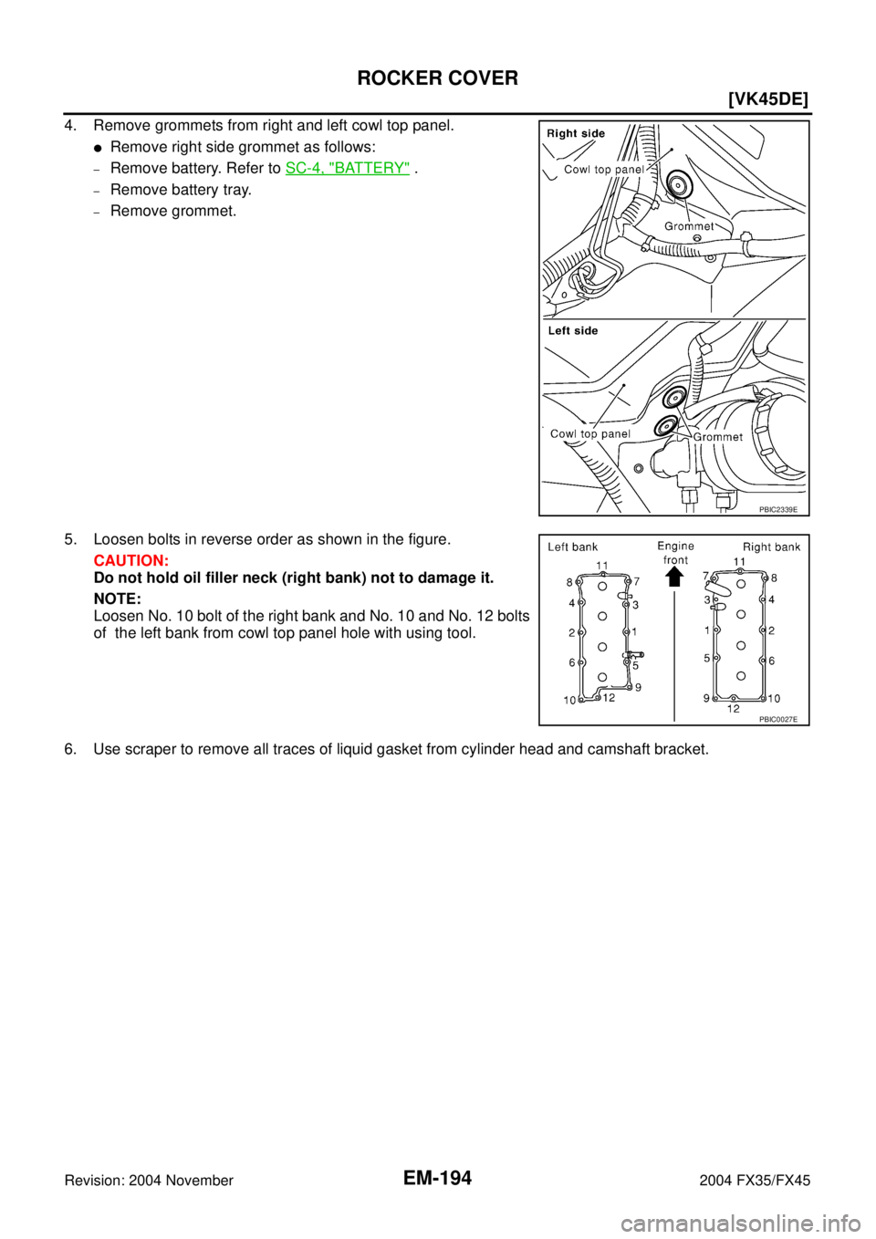
4. Remove grommets from right and left cowl top panel.
�Remove right side grommet as follows:
–Remove battery. Refer to SC-4, "BATTERY" .
–Remove battery tray.
–Remove grommet.
5. Loosen bolts in reverse order as shown in the figure.
CAUTION:
Do not hold oil filler neck (right bank) not to damage it.
NOTE:
Loosen No. 10 bolt of the right bank and No. 10 and No. 12 bolts
of the left bank from cowl top panel hole with using tool.
6. Use scraper to remove all traces of liquid gasket from cylinder head and camshaft bracket.
PBIC2339E
PBIC0027E
Page 2920 of 4449
![INFINITI FX35 2004 Service Manual ROCKER COVER
EM-195
[VK45DE]
C
D
E
F
G
H
I
J
K
L
MA
EM
Revision: 2004 November 2004 FX35/FX45
INSTALLATION
1. Apply liquid gasket to joint part of cylinder head and camshaft
bracket as follows:
NOTE:](/manual-img/42/57021/w960_57021-2919.png "INFINITI FX35 2004 Service Manual ROCKER COVER
EM-195
[VK45DE]
C
D
E
F
G
H
I
J
K
L
MA
EM
Revision: 2004 November 2004 FX35/FX45
INSTALLATION
1. Apply liquid gasket to joint part of cylinder head and camshaft
bracket as follows:
NOTE:")
ROCKER COVER
EM-195
[VK45DE]
C
D
E
F
G
H
I
J
K
L
MA
EM
Revision: 2004 November 2004 FX35/FX45
INSTALLATION
1. Apply liquid gasket to joint part of cylinder head and camshaft
bracket as follows:
NOTE:
The figure shows an example of left bank side [zoomed in
shows camshaft bracket (No. 1)]. Apply only to camshaft bracket
(No. 1) for right bank side.
a. Refer to the figure “a” to apply liquid gasket to joint part of cam-
shaft bracket (both No. 1 and No. 6) and cylinder head.
b. Refer to the figure “b” to apply liquid gasket in 90 degrees to the
figure “a”.
Use Genuine RTV Silicone Sealant or equivalent. Refer to
GI-48, "
RECOMMENDED CHEMICAL PRODUCTS AND
SEALANTS" .
2. Install rocker cover.
�Check if rocker cover gasket is not dropped from installation groove of rocker cover.
3. Tighten bolts in two steps separately in numerical order as
shown in the figure.
CAUTION:
Do not hold oil filler neck (right bank) not to damage it.
NOTE:
Tighten No. 10 bolt of the right bank and No. 10 and No. 12 bolts
of the left bank from cowl top panel hole with using tool.
4. Install in the reverse order of removal after this step.
PBIC2444E
1st step : 2.0 N·m (0.2 kg-m, 18 in-lb)
2nd step : 8.3 N·m (0.85 kg-m, 73 in-lb)
PBIC0027E
Page 2923 of 4449
![INFINITI FX35 2004 Service Manual EM-198
[VK45DE]
TIMING CHAIN
Revision: 2004 November 2004 FX35/FX45
5. Remove intake valve timing control cover as follows:
a. Loosen and remove mounting bolts in the reverse order as
shown in the fi](/manual-img/42/57021/w960_57021-2922.png "INFINITI FX35 2004 Service Manual EM-198
[VK45DE]
TIMING CHAIN
Revision: 2004 November 2004 FX35/FX45
5. Remove intake valve timing control cover as follows:
a. Loosen and remove mounting bolts in the reverse order as
shown in the fi")
EM-198
[VK45DE]
TIMING CHAIN
Revision: 2004 November 2004 FX35/FX45
5. Remove intake valve timing control cover as follows:
a. Loosen and remove mounting bolts in the reverse order as
shown in the figure.
b . U s e s e a l c u t t e r [ S S T: K V 1 0 1111 0 0 ( J 3 7 2 2 8 ) ] o r e q u i v a l e n t t o o l
to cut liquid gasket for removal.
CAUTION:
�Exercise care not to damage mating surfaces.
�Pull out cover keeping levelness without an angle, as
inner part of cover is engaged with the center of camshaft
sprocket (INT).
6. Remove O-rings from front cover.
7. Obtain No. 1 cylinder at TDC of its compression stroke as follows:
a. Rotate crankshaft pulley clockwise to align the TDC identifica-
tion notch (without paint mark) with timing indicator on front
cover.
b. Make sure that both intake and exhaust cam noses of No. 1 cyl-
inder (engine front side of left bank) are located as shown in the
figure.
�If not, turn crankshaft pulley one revolution (360 degrees) and
align as shown in the figure.
8. Remove crankshaft pulley as follows:
PBIC0051E
SBIA0374E
PBIC2341E
KBIA0400J
Page 2924 of 4449
![INFINITI FX35 2004 Service Manual TIMING CHAIN
EM-199
[VK45DE]
C
D
E
F
G
H
I
J
K
L
MA
EM
Revision: 2004 November 2004 FX35/FX45
a. Remove rear plate cover, and set ring gear stopper (SST).
b. Loosen crankshaft pulley bolt, and then pu](/manual-img/42/57021/w960_57021-2923.png "INFINITI FX35 2004 Service Manual TIMING CHAIN
EM-199
[VK45DE]
C
D
E
F
G
H
I
J
K
L
MA
EM
Revision: 2004 November 2004 FX35/FX45
a. Remove rear plate cover, and set ring gear stopper (SST).
b. Loosen crankshaft pulley bolt, and then pu")
TIMING CHAIN
EM-199
[VK45DE]
C
D
E
F
G
H
I
J
K
L
MA
EM
Revision: 2004 November 2004 FX35/FX45
a. Remove rear plate cover, and set ring gear stopper (SST).
b. Loosen crankshaft pulley bolt, and then pull crankshaft pulley
with both hands to remove it.
CAUTION:
�Do not remove crankshaft pulley bolt. Keep loosened
crankshaft pulley bolt in place to protect removed crank-
shaft pulley from dropping.
�Do not remove balance weight (inner hexagon bolt) at the
front of crankshaft pulley.
9. Remove oil pan and oil strainer. Refer to EM-181, "
OIL PAN AND OIL STRAINER" .
10. Remove front cover as follows:
a. Loosen mounting bolts in reverse order as shown in the figure.
b . U s e s e a l c u t t e r [ S S T: K V 1 0 1111 0 0 ( J 3 7 2 2 8 ) ] o r e q u i v a l e n t t o o l
to cut liquid gasket for removal.
CAUTION:
�Exercise care not to damage mating surfaces.
�After removal, handle front cover carefully so it does not
tilt, cant, or warp under a load.
11. Remove front oil seal from front cover using suitable tool.
�Use flat-blade screwdriver for removal.
CAUTION:
Be careful not to damage front cover.
12. Remove O-rings from cylinder heads (right and left bank) and
cylinder block.
13. Remove chain tensioner cover from front cover.
�U s e s e a l c u t t e r [ S S T: K V 1 0 1111 0 0 ( J 3 7 2 2 8 ) ] o r e q u i v a l e n t t o o l t o c u t l i q u i d g a s k e t f o r r e m o v e .
14. Remove oil pump drive spacer.
�Set bolts in the two bolt holes [M6 × pitch 1.0 mm (0.04 in)] on
front surface. Using suitable puller, pull oil pump drive spacer
off from crankshaft.
NOTE:
The dimension between the centers of the two bolt holes is 33
mm (1.30 in).
In the figure, a commercial steering puller is used.
15. Remove oil pump. Refer to LU-31, "
OIL PUMP" .
16. Remove chain tensioner (left bank) as follows:
PBIC1656E
KBIA0354J
SBIA0373E
PBIC2342E
Page 2925 of 4449
![INFINITI FX35 2004 Service Manual EM-200
[VK45DE]
TIMING CHAIN
Revision: 2004 November 2004 FX35/FX45
NOTE:
To remove timing chain and related parts, start with those on left bank. The procedure for removing parts
on right bank is omi](/manual-img/42/57021/w960_57021-2924.png "INFINITI FX35 2004 Service Manual EM-200
[VK45DE]
TIMING CHAIN
Revision: 2004 November 2004 FX35/FX45
NOTE:
To remove timing chain and related parts, start with those on left bank. The procedure for removing parts
on right bank is omi")
EM-200
[VK45DE]
TIMING CHAIN
Revision: 2004 November 2004 FX35/FX45
NOTE:
To remove timing chain and related parts, start with those on left bank. The procedure for removing parts
on right bank is omitted because it is the same as that for left bank.
a. Press tab in the direction of arrow (or turn lever in the direction
of arrow) to unlock the locking with the groove that stops ten-
sioner plunger from returning.
�Lightly press tensioner plunger to release the tension of
spring for this operation.
b. Push in tensioner plunger to align the hole on lever and that on
pump main body.
�Pushing in tensioner too far does not allow the holes to align.
Therefore, push in plunger to the degree at which the start of
stopper groove and tab engages.
c. Insert stopper pin [hard wire with approx. 0.5 mm (0.020 in)
diameter or similar tool] to fix plunger. With plunger fixed, remove chain tensioner.
17. Remove chain tension guide and timing chain slack guide.
18. Remove timing chain and crankshaft sprocket.
CAUTION:
After removing timing chain, do not turn crankshaft and camshaft separately, or valves will strike
the piston head.
19. With hexagonal part of camshaft locked with wrench, loosen
bolts securing camshaft sprocket to remove camshaft sprocket.
20. Perform same procedure as for left bank, remove timing chain and related parts on right side.
21. Use scraper to remove all traces of old liquid gasket from front cover and opposite mating surfaces.
�Remove oil liquid gasket from bolt hole and thread.
22. Use scraper to remove all trace of liquid gasket from chain tensioner cover and intake valve timing control
covers.
PBIC2343E
PBIC0030E
PBIC2084E
Page 2929 of 4449
![INFINITI FX35 2004 Service Manual EM-204
[VK45DE]
TIMING CHAIN
Revision: 2004 November 2004 FX35/FX45
7. Install oil pump drive spacer as follows:
a. Insert oil pump drive spacer according to the directions of crank-
shaft key and the](/manual-img/42/57021/w960_57021-2928.png "INFINITI FX35 2004 Service Manual EM-204
[VK45DE]
TIMING CHAIN
Revision: 2004 November 2004 FX35/FX45
7. Install oil pump drive spacer as follows:
a. Insert oil pump drive spacer according to the directions of crank-
shaft key and the")
EM-204
[VK45DE]
TIMING CHAIN
Revision: 2004 November 2004 FX35/FX45
7. Install oil pump drive spacer as follows:
a. Insert oil pump drive spacer according to the directions of crank-
shaft key and the two flat surfaces of oil pump inner rotor.
�If the positional relationship does not allow the insertion,
rotate oil pump inner rotor with a finger to allow spacer.
b. After confirming that the position of each part is in correct condi-
tion to allow for spacer, force fit spacer by lightly tapping with
plastic hammer until it contacts and does not go further.
8. Install front oil seal on front cover.
�Apply new engine oil to both oil seal lip and dust seal lip.
�Install it so that each seal lip is oriented as shown in the fig-
ure.
CAUTION:
Be careful not to scratch or make burrs on circumference
of oil seal.
�Using suitable drift, press fit until the height of front oil seal is
level with the mounting surface.
�Make sure the garter spring is in position and seal lips not
inverted.
9. Install chain tensioner cover to front cover.
�Apply a continuous bead of liquid gasket with tube presser
[SST: WS39930000 ( — )] to front cover as shown in the
figure.
Use Genuine RTV Silicone Sealant or equivalent. Refer to
GI-48, "
RECOMMENDED CHEMICAL PRODUCTS AND
SEALANTS" .
10. Install front cover as follows:
PBIC0058E
SEM715A
Suitable drift
Outer diameter : 56 mm (2.20 in)
Inner diameter : 49 mm (1.93 in)
PBIC0059E
SBIA0372E
Page 2930 of 4449
![INFINITI FX35 2004 Service Manual TIMING CHAIN
EM-205
[VK45DE]
C
D
E
F
G
H
I
J
K
L
MA
EM
Revision: 2004 November 2004 FX35/FX45
a. Install new O-rings onto cylinder heads (right and left bank) and
cylinder block.
b. Apply a continuous](/manual-img/42/57021/w960_57021-2929.png "INFINITI FX35 2004 Service Manual TIMING CHAIN
EM-205
[VK45DE]
C
D
E
F
G
H
I
J
K
L
MA
EM
Revision: 2004 November 2004 FX35/FX45
a. Install new O-rings onto cylinder heads (right and left bank) and
cylinder block.
b. Apply a continuous")
TIMING CHAIN
EM-205
[VK45DE]
C
D
E
F
G
H
I
J
K
L
MA
EM
Revision: 2004 November 2004 FX35/FX45
a. Install new O-rings onto cylinder heads (right and left bank) and
cylinder block.
b. Apply a continuous bead of liquid gasket with tube presser
[SST: WS39930000 ( — )] to front cover as shown in the fig-
ure.
Use Genuine RTV Silicone Sealant or equivalent. Refer to
GI-48, "
RECOMMENDED CHEMICAL PRODUCTS AND
SEALANTS" .
c. make sure again that the mating marks on timing chain and that
on each sprocket are aligned. Then, install front cover.
CAUTION:
Be careful to avoid interference with the front end of oil
pump drive spacer. Such interference may damage front oil
seal.
d. Tighten mounting bolts in numerical order as shown in the fig-
ure.
�There are four type mounting bolts.
e. After all bolts are tightened, retighten them in numerical order as shown in the figure.
CAUTION:
Be sure to wipe off any excessive liquid gasket leaking onto surface mating with oil pan.
11. Install intake valve timing control cover as follows:
a. At the back of intake valve timing control cover, install new seal rings (three for each bank) to the area to
be inserted into camshaft sprocket (INT).
CAUTION:
Do not spread seal ring excessively to avoid breaks and deformation.
SBIA0373E
PBIC0062E
KBIA0354J
PBIC1681E