Page 2844 of 4449
ENGINE ASSEMBLY
EM-119
[VQ35DE]
C
D
E
F
G
H
I
J
K
L
MA
EM
Revision: 2004 November 2004 FX35/FX45
Fuel — Leakage —
Exhaust gas — Leakage —
Page 2846 of 4449
![INFINITI FX35 2004 Service Manual CYLINDER BLOCK
EM-121
[VQ35DE]
C
D
E
F
G
H
I
J
K
L
MA
EM
Revision: 2004 November 2004 FX35/FX45
DISASSEMBLY
1. Remove engine assembly from vehicle, and separate transmission from engine. Refer to EM-1](/manual-img/42/57021/w960_57021-2845.png "INFINITI FX35 2004 Service Manual CYLINDER BLOCK
EM-121
[VQ35DE]
C
D
E
F
G
H
I
J
K
L
MA
EM
Revision: 2004 November 2004 FX35/FX45
DISASSEMBLY
1. Remove engine assembly from vehicle, and separate transmission from engine. Refer to EM-1")
CYLINDER BLOCK
EM-121
[VQ35DE]
C
D
E
F
G
H
I
J
K
L
MA
EM
Revision: 2004 November 2004 FX35/FX45
DISASSEMBLY
1. Remove engine assembly from vehicle, and separate transmission from engine. Refer to EM-110,
"ENGINE ASSEMBLY" .
2. Remove engine mounting bracket. Refer to EM-110, "
ENGINE ASSEMBLY" .
3. Remove RH side exhaust manifold. Refer to EM-26, "
EXHAUST MANIFOLD AND THREE WAY CATA-
LYST" .
4. Install engine sub-attachment with engine stand shaft (SST) to
right side of cylinder block.
�Use spacer to engine rear side.
1. Cylinder block 2. Reinforcement plate 3. Drive plate
4. Rear oil seal retainer 5. Cover 6. Gasket
7. Knock sensor 8. Oil jet 9. Thrust bearing
10. Pilot converter 11. Main bearing 12. Crankshaft
13. Key 14. Main bearing cap 15. Main bearing cap bolt
16. Main bearing beam 17. Baffle plate (2WD model) 18. Top ring
19. Second ring 20. Oil ring 21. Piston
22. Piston pin 23. Snap ring 24. Connecting rod
25. Connecting rod bearing 26. Connecting rod bearing cap 27. Connecting rod bolt
1. Cylinder block 2. Gasket 3. Water connector
4. Gasket 5. Cylinder block heater 6. Connector protector cap
PBIC2614E
SBIA0503E
Page 2849 of 4449
![INFINITI FX35 2004 Service Manual EM-124
[VQ35DE]
CYLINDER BLOCK
Revision: 2004 November 2004 FX35/FX45
12. Use a seal cutter (SST) to cut away liquid gasket and remove
rear oil seal retainer.
CAUTION:
�Be careful not to damage mounti](/manual-img/42/57021/w960_57021-2848.png "INFINITI FX35 2004 Service Manual EM-124
[VQ35DE]
CYLINDER BLOCK
Revision: 2004 November 2004 FX35/FX45
12. Use a seal cutter (SST) to cut away liquid gasket and remove
rear oil seal retainer.
CAUTION:
�Be careful not to damage mounti")
EM-124
[VQ35DE]
CYLINDER BLOCK
Revision: 2004 November 2004 FX35/FX45
12. Use a seal cutter (SST) to cut away liquid gasket and remove
rear oil seal retainer.
CAUTION:
�Be careful not to damage mounting surface.
�If rear oil seal retainer is removed, replace it with a new
one.
NOTE:
Rear oil seal and retainer make up a single part and are
removed as an assembly.
13. Remove baffle plate from main bearing beam (2WD model).
14. Remove piston and connecting rod assembly.
�Before removing piston and connecting rod assembly, check
connecting rod side clearance. Refer to EM-136, "
CONNECT-
ING ROD SIDE CLEARANCE" .
a. Position crankshaft pin corresponding to connecting rod to be
removed onto the bottom dead center.
b. Remove connecting rod cap.
c. Using a hammer handle or similar tool, push piston and connect-
ing rod assembly out to cylinder head side.
15. Remove connecting rod bearings from connecting rod and con-
necting rod cap.
CAUTION:
When removing them, note the installation position. Keep them in the correct order.
16. Remove piston rings form piston.
�Use a piston ring expander (commercial service tool).
CAUTION:
�When removing piston rings, be careful not to damage
piston.
�Be careful not to damage piston rings by expanding
them excessively.
17. Remove piston from connecting rod as follows.
a. Using a snap ring pliers, remove snap ring.
SEM830E
EMQ0191D
PBIC0087E
PBIC0088E
Page 2851 of 4449
![INFINITI FX35 2004 Service Manual EM-126
[VQ35DE]
CYLINDER BLOCK
Revision: 2004 November 2004 FX35/FX45
ASSEMBLY
1. Fully air-blow engine coolant and engine oil passages in cylinder block, cylinder bore and crankcase to
remove any for](/manual-img/42/57021/w960_57021-2850.png "INFINITI FX35 2004 Service Manual EM-126
[VQ35DE]
CYLINDER BLOCK
Revision: 2004 November 2004 FX35/FX45
ASSEMBLY
1. Fully air-blow engine coolant and engine oil passages in cylinder block, cylinder bore and crankcase to
remove any for")
EM-126
[VQ35DE]
CYLINDER BLOCK
Revision: 2004 November 2004 FX35/FX45
ASSEMBLY
1. Fully air-blow engine coolant and engine oil passages in cylinder block, cylinder bore and crankcase to
remove any foreign material.
CAUTION:
Use a goggles to protect your eye.
2. Install each water drain plug to cylinder block as shown in the
figure.
�Apply liquid gasket to the thread of water drain plugs.
Use Genuine RTV Silicone Sealant or equivalent. Refer to
GI-48, "
RECOMMENDED CHEMICAL PRODUCTS AND
SEALANTS" .
3. Install each plug to cylinder block as shown in the figure if
removed.
�Apply liquid gasket to the thread of plugs and install plugs with
new gaskets.
Use Genuine High Strength Thread Locking Sealant or
equivalent. Refer to GI-48, "
RECOMMENDED CHEMICAL
PRODUCTS AND SEALANTS" .
Use Genuine RTV Silicone Sealant or equivalent. Refer to GI-48, "
RECOMMENDED CHEMICAL
PRODUCTS AND SEALANTS" .
4. Install oil jet.
�Insert oil jet dowel pin into cylinder block dowel pin hole, and
tighten mounting bolts.Water drain plug (front) “A”:
: 9.8 N·m (1.0 kg-m, 87 in-lb)
Water drain plug (RH) “B”:
: 19.6 N·m (2.0 kg-m, 14 ft-lb)
Water drain plug (LH) “C”:
: 19.6 N·m (2.0 kg-m, 14 ft-lb)
Plug (RH) “D”:
: 12.3 N·m (1.3 kg-m, 9 ft-lb)
Plug (rear) “E”:
: 62 N·m (6.3 kg-m, 46 ft-lb)
Plug (LH) “F”:
: 62 N·m (6.3 kg-m, 46 ft-lb)
PBIC2610E
PBIC0898E
Page 2855 of 4449
EM-130
[VQ35DE]
CYLINDER BLOCK
Revision: 2004 November 2004 FX35/FX45
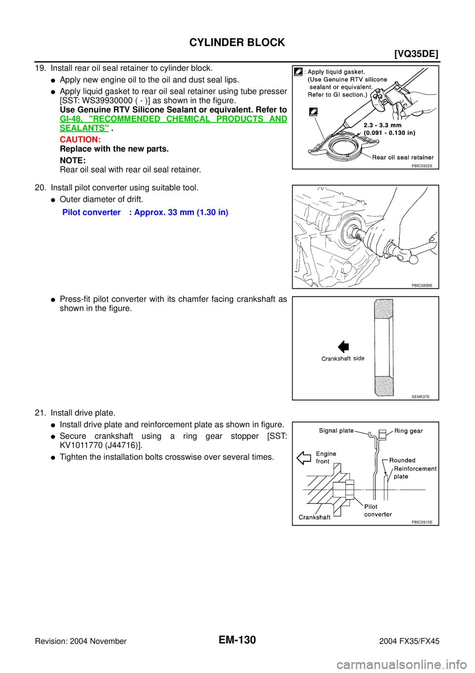
19. Install rear oil seal retainer to cylinder block.
�Apply new engine oil to the oil and dust seal lips.
�Apply liquid gasket to rear oil seal retainer using tube presser
[SST: WS39930000 ( - )] as shown in the figure.
Use Genuine RTV Silicone Sealant or equivalent. Refer to
GI-48, "
RECOMMENDED CHEMICAL PRODUCTS AND
SEALANTS" .
CAUTION:
Replace with the new parts.
NOTE:
Rear oil seal with rear oil seal retainer.
20. Install pilot converter using suitable tool.
�Outer diameter of drift.
�Press-fit pilot converter with its chamfer facing crankshaft as
shown in the figure.
21. Install drive plate.
�Install drive plate and reinforcement plate as shown in figure.
�Secure crankshaft using a ring gear stopper [SST:
KV1011770 (J44716)].
�Tighten the installation bolts crosswise over several times.
PBIC0922E
Pilot converter : Approx. 33 mm (1.30 in)
PBIC0899E
SEM537E
PBIC0910E
Page 2864 of 4449
![INFINITI FX35 2004 Service Manual CYLINDER BLOCK
EM-139
[VQ35DE]
C
D
E
F
G
H
I
J
K
L
MA
EM
Revision: 2004 November 2004 FX35/FX45
Piston Pin Outer Diameter
Measure outer diameter of piston pin.
Connecting Rod Bushing Oil Clearance (Sm](/manual-img/42/57021/w960_57021-2863.png "INFINITI FX35 2004 Service Manual CYLINDER BLOCK
EM-139
[VQ35DE]
C
D
E
F
G
H
I
J
K
L
MA
EM
Revision: 2004 November 2004 FX35/FX45
Piston Pin Outer Diameter
Measure outer diameter of piston pin.
Connecting Rod Bushing Oil Clearance (Sm")
CYLINDER BLOCK
EM-139
[VQ35DE]
C
D
E
F
G
H
I
J
K
L
MA
EM
Revision: 2004 November 2004 FX35/FX45
Piston Pin Outer Diameter
Measure outer diameter of piston pin.
Connecting Rod Bushing Oil Clearance (Small End)
(Connecting rod bushing oil clearance) = (Piston pin bushing inner diameter) – (Piston pin outer diameter)
�If the measured value exceeds the standard, replace connecting rod assembly and/or piston and piston
pin assembly.
�If replacing piston and piston pin assembly, refer to EM-140, "PISTON TO CYLINDER BORE CLEAR-
ANCE" .
�If replacing connecting rod assembly, refer to EM-142, "CON-
NECTING ROD BEARING OIL CLEARANCE" .
Factory installed parts grading:
Service parts apply only to grade “0”.
Unit: mm (in)
*: After installing in connecting rod
CYLINDER BLOCK DISTORTION
�Using a scraper, remove gasket on the cylinder block surface, and also remove engine oil, scale, carbon,
or other contamination.
CAUTION:
Be careful not to allow gasket flakes to enter engine oil or engine coolant passages.Standard : 21.989 - 22.001 mm (0.8657 - 0.8662 in)
PBIC0117E
Standard : 0.005 - 0.017 mm (0.0002 - 0.0007 in)
Limit : 0.030 mm (0.0012 in)
PBIC0809E
Grade 0 1
Piston pin bushing inner
diameter* 22.000 - 22.006
(0.8661 - 0.8664) 22.006 - 22.012
(0.8664 - 0.8666)
Piston pin hole diameter 21.993 - 21.999
(0.8659 - 0.8661) 21.999 - 22. 005
(0.8661 - 0.8663)
Piston pin outer diameter 21.989 - 21.995
(0.8657- 0.8659) 21.995 - 22.001
(0.8659 - 0.8662)
PBIC0812E
Page 2885 of 4449
![INFINITI FX35 2004 Service Manual EM-160
[VK45DE]
PRECAUTIONS
Revision: 2004 November 2004 FX35/FX45
�When tightening nuts and bolts, as a basic rule, equally tighten in several different steps starting with the
ones in center, then o](/manual-img/42/57021/w960_57021-2884.png "INFINITI FX35 2004 Service Manual EM-160
[VK45DE]
PRECAUTIONS
Revision: 2004 November 2004 FX35/FX45
�When tightening nuts and bolts, as a basic rule, equally tighten in several different steps starting with the
ones in center, then o")
EM-160
[VK45DE]
PRECAUTIONS
Revision: 2004 November 2004 FX35/FX45
�When tightening nuts and bolts, as a basic rule, equally tighten in several different steps starting with the
ones in center, then ones on inside and outside diagonally in this order. If the order of tightening is speci-
fied, do exactly as specified.
�Replace with new gasket, packing, oil seal or O-ring.
�Thoroughly wash, clean, and air-blow each part. Carefully check engine oil or engine coolant passages for
any restriction and blockage.
�Avoid damaging sliding or mating surfaces. Completely remove foreign materials such as cloth lint or dust.
Before assembly, oil sliding surfaces well.
�Release air within route when refilling after draining engine coolant.
�After repairing, start engine and increase engine speed to check engine coolant, fuel, oil, and exhaust
systems for leakage.
Parts Requiring Angle TighteningABS006I0
�Use angle wrench [SST: KV10112100 (BT8653-A)] for the final tightening of the following engine parts:
–Cylinder head bolts
–Main bearing cap bolts
–Connecting rod cap nuts
–Crankshaft pulley bolt (No angle wrench is required as the bolt flange is provided with notches for angle
tightening)
�Do not use a torque value for final tightening.
�The torque value for these parts are for a preliminary step.
�Ensure thread and seat surfaces are clean and coated with engine oil.
Precautions for Liquid GasketABS006I1
REMOVAL OF LIQUID GASKET SEALING
�After removing mounting bolts and nuts, separate the mating
surface using seal cutter (SST) and remove old liquid gasket
sealing.
CAUTION:
Be careful not to damage the mating surfaces.
�In areas where seal cutter (SST) is difficult to use, use plastic
hammer to lightly tap the areas where liquid gasket is applied.
CAUTION:
If for some unavoidable reason tool such as a flat-blade
screwdriver is used, be careful not to damage the mating
surfaces.
LIQUID GASKET APPLICATION PROCEDURE
1. Using scraper, remove old liquid gasket adhering to the liquid
gasket application surface and the mating surface.
�Remove liquid gasket completely from the groove of the liquid
gasket application surface, mounting bolts, and bolt holes.
2. Wipe the liquid gasket application surface and the mating sur-
face with white gasoline (lighting and heating use) to remove
adhering moisture, grease and foreign materials.
PBIC0002E
PBIC0003E
Page 2886 of 4449
![INFINITI FX35 2004 Service Manual PRECAUTIONS
EM-161
[VK45DE]
C
D
E
F
G
H
I
J
K
L
MA
EM
Revision: 2004 November 2004 FX35/FX45
3. Attach liquid gasket tube to tube presser [SST: WS39930000
(—)].
Use Genuine RTV Silicone Sealant or e](/manual-img/42/57021/w960_57021-2885.png "INFINITI FX35 2004 Service Manual PRECAUTIONS
EM-161
[VK45DE]
C
D
E
F
G
H
I
J
K
L
MA
EM
Revision: 2004 November 2004 FX35/FX45
3. Attach liquid gasket tube to tube presser [SST: WS39930000
(—)].
Use Genuine RTV Silicone Sealant or e")
PRECAUTIONS
EM-161
[VK45DE]
C
D
E
F
G
H
I
J
K
L
MA
EM
Revision: 2004 November 2004 FX35/FX45
3. Attach liquid gasket tube to tube presser [SST: WS39930000
(—)].
Use Genuine RTV Silicone Sealant or equivalent. Refer to
GI-48, "
RECOMMENDED CHEMICAL PRODUCTS AND
SEALANTS" .
4. Apply liquid gasket without breaks to the specified location with the specified dimensions.
�If there is a groove for the liquid gasket application, apply liquid gasket to the groove.
�As for the bolt holes, normally apply liquid gasket inside the
holes. Occasionally, it should be applied outside the holes.
Make sure to read the text of this manual.
�Within five minutes of liquid gasket application, install the mat-
ing component.
�If liquid gasket protrudes, wipe it off immediately.
�Do not retighten after the installation.
�Wait 30 minutes or more after installation before refilling
engine with engine oil and engine coolant.
CAUTION:
If there are specific instructions in this manual, observe
them.
EMA0622D
SEM159F
![INFINITI FX35 2004 Service Manual ENGINE ASSEMBLY
EM-119
[VQ35DE]
C
D
E
F
G
H
I
J
K
L
MA
EM
Revision: 2004 November 2004 FX35/FX45
Fuel — Leakage —
Exhaust gas — Leakage —](/manual-img/42/57021/w960_57021-2843.png "INFINITI FX35 2004 Service Manual ENGINE ASSEMBLY
EM-119
[VQ35DE]
C
D
E
F
G
H
I
J
K
L
MA
EM
Revision: 2004 November 2004 FX35/FX45
Fuel — Leakage —
Exhaust gas — Leakage —")