Page 2797 of 4449
EM-72
[VQ35DE]
TIMING CHAIN
Revision: 2004 November 2004 FX35/FX45
1. Install timing chain tensioners (secondary) to cylinder head as the following if removed. Refer to EM-87,
"INSTALLATION" .
a. Install chain tensioners with stopper pin attached and new O-rings.
b. Install No. 1 camshaft brackets. Refer to EM-87, "
INSTALLATION" .
2. Install new O-rings onto cylinder block.
3. Install new O-rings to cylinder head.
4. Apply liquid gasket to rear timing chain case back side as shown with tube presser [SST: WS39930000 ( –
)].
Use Genuine RTV Silicone Sealant or equivalent. Refer to GI-48, "
RECOMMENDED CHEMICAL
PRODUCTS AND SEALANTS".
CAUTION:
�For “A” in the figure, completely wipe out liquid gasket extended on a portion touching at
engine coolant.
PBIC0788E
SBIA0496E
Page 2798 of 4449
TIMING CHAIN
EM-73
[VQ35DE]
C
D
E
F
G
H
I
J
K
L
MA
EM
Revision: 2004 November 2004 FX35/FX45
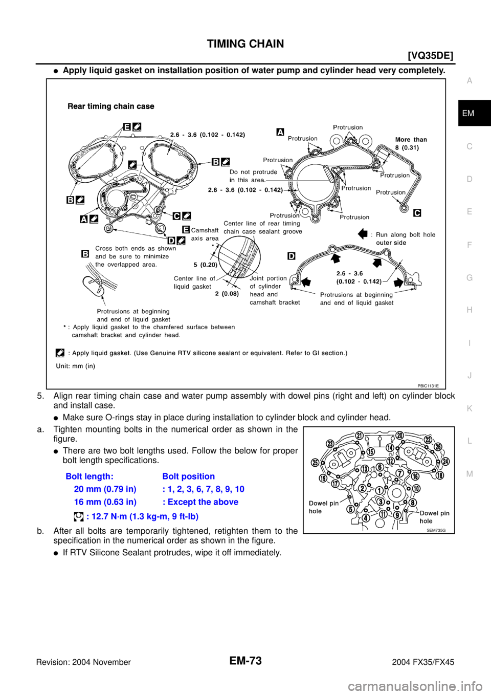
�Apply liquid gasket on installation position of water pump and cylinder head very completely.
5. Align rear timing chain case and water pump assembly with dowel pins (right and left) on cylinder block
and install case.
�Make sure O-rings stay in place during installation to cylinder block and cylinder head.
a. Tighten mounting bolts in the numerical order as shown in the
figure.
�There are two bolt lengths used. Follow the below for proper
bolt length specifications.
b. After all bolts are temporarily tightened, retighten them to the
specification in the numerical order as shown in the figure.
�If RTV Silicone Sealant protrudes, wipe it off immediately.Bolt length: Bolt position
20 mm (0.79 in) : 1, 2, 3, 6, 7, 8, 9, 10
16 mm (0.63 in) : Except the above
: 12.7 N·m (1.3 kg-m, 9 ft-lb)
PBIC1131E
SEM735G
Page 2803 of 4449
EM-78
[VQ35DE]
TIMING CHAIN
Revision: 2004 November 2004 FX35/FX45
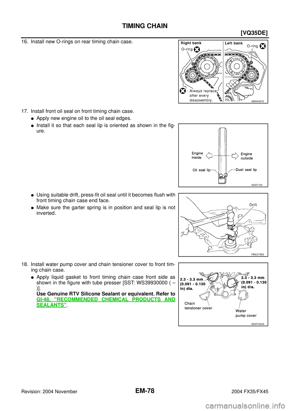
16. Install new O-rings on rear timing chain case.
17. Install front oil seal on front timing chain case.
�Apply new engine oil to the oil seal edges.
�Install it so that each seal lip is oriented as shown in the fig-
ure.
�Using suitable drift, press-fit oil seal until it becomes flush with
front timing chain case end face.
�Make sure the garter spring is in position and seal lip is not
inverted.
18. Install water pump cover and chain tensioner cover to front tim-
ing chain case.
�Apply liquid gasket to front timing chain case front side as
shown in the figure with tube presser [SST: WS39930000 ( –
)].
Use Genuine RTV Silicone Sealant or equivalent. Refer to
GI-48, "
RECOMMENDED CHEMICAL PRODUCTS AND
SEALANTS".
SBIA0497E
SEM715A
PBIC0790E
SEM744GA
Page 2804 of 4449
![INFINITI FX35 2004 Service Manual TIMING CHAIN
EM-79
[VQ35DE]
C
D
E
F
G
H
I
J
K
L
MA
EM
Revision: 2004 November 2004 FX35/FX45
19. Install front timing chain case as follows:
a. Apply liquid gasket to front timing chain case back side](/manual-img/42/57021/w960_57021-2803.png "INFINITI FX35 2004 Service Manual TIMING CHAIN
EM-79
[VQ35DE]
C
D
E
F
G
H
I
J
K
L
MA
EM
Revision: 2004 November 2004 FX35/FX45
19. Install front timing chain case as follows:
a. Apply liquid gasket to front timing chain case back side")
TIMING CHAIN
EM-79
[VQ35DE]
C
D
E
F
G
H
I
J
K
L
MA
EM
Revision: 2004 November 2004 FX35/FX45
19. Install front timing chain case as follows:
a. Apply liquid gasket to front timing chain case back side as
shown in the figure with tube presser [SST: WS39930000 ( – )].
Use Genuine RTV Silicone Sealant or equivalent. Refer to
GI-48, "
RECOMMENDED CHEMICAL PRODUCTS AND
SEALANTS".
b. Install dowel pin on rear timing chain case into dowel pin hole on
front timing chain case.
c. Tighten bolts to the specified torque in order as shown in the fig-
ure.
d. After tightening, retighten them to specified torque in numerical
order shown in figure.
20. After installing front timing chain case, check the surface height
difference between the following parts on the oil pan mounting
surface.
�If not within specification, repeat the installation procedure.
21. Install right and left intake valve timing control covers as follows:
a. Install seal rings in shaft grooves.
b. Apply liquid gasket to intake valve timing control covers as
shown in the figure with tube presser [SST: WS39930000 ( – )].
Use Genuine RTV Silicone Sealant or equivalent. Refer to
GI-48, "
RECOMMENDED CHEMICAL PRODUCTS AND
SEALANTS".
PBIC1133E
8 mm (0.31 in) dia. bolts : 1, 2
: 28.4 N·m (2.9 kg-m, 21 ft-lb)
6 mm (0.24 in) dia. bolts : Except the above
: 12.7 N·m (1.3 kg-m, 9 ft-lb)
KBIA1303E
Standard
Front timing chain case to rear timing chain case:
–0.14 to 0.14 mm (–0.005 to 0.0055 in)
SEM943G
SBIA0492E
Page 2806 of 4449
TIMING CHAIN
EM-81
[VQ35DE]
C
D
E
F
G
H
I
J
K
L
MA
EM
Revision: 2004 November 2004 FX35/FX45
�Warm up engine thoroughly to make sure there is no leakage of engine coolant, engine oil and working
fluid, fuel and exhaust gas.
�Bleed air from passages in pipes and tubes of applicable lines, such as in cooling system.
�After cooling down engine, again check amounts of engine coolant, engine oil and working fluid. Refill to
specified level, if necessary.
Summary of the inspection items:
Item Before starting engine Engine running After engine stopped
Engine coolant Level Leakage Level
Engine oil Level Leakage Level
Working fluid Level Leakage Level
Page 2807 of 4449
EM-82
[VQ35DE]
CAMSHAFT
Revision: 2004 November 2004 FX35/FX45
CAMSHAFTPFP:13001
Removal and InstallationABS00FPH
1.Intake valve timing control solenoid
valve2. Gasket 3. Camshaft bracket (No. 2 to No. 4)
4. Camshaft (EXH) 5. Camshaft (INT) 6. Camshaft bracket (No. 1)
7. Dowel pin 8. Valve lifter 9. O-ring
10. Chain tensioner 11. Spring 12. Plunger
13. Cylinder head (right bank) 14. Cylinder head (left bank) 15.Camshaft position sensor (PHASE)
(right bank)
16.Camshaft position sensor (PHASE)
(left bank)
SBIA0576E
Page 2814 of 4449
![INFINITI FX35 2004 Service Manual CAMSHAFT
EM-89
[VQ35DE]
C
D
E
F
G
H
I
J
K
L
MA
EM
Revision: 2004 November 2004 FX35/FX45
5. Tighten camshaft brackets in the following steps, in numerical
order as shown in the figure.
a. Tighten No.](/manual-img/42/57021/w960_57021-2813.png "INFINITI FX35 2004 Service Manual CAMSHAFT
EM-89
[VQ35DE]
C
D
E
F
G
H
I
J
K
L
MA
EM
Revision: 2004 November 2004 FX35/FX45
5. Tighten camshaft brackets in the following steps, in numerical
order as shown in the figure.
a. Tighten No.")
CAMSHAFT
EM-89
[VQ35DE]
C
D
E
F
G
H
I
J
K
L
MA
EM
Revision: 2004 November 2004 FX35/FX45
5. Tighten camshaft brackets in the following steps, in numerical
order as shown in the figure.
a. Tighten No. 7 to 10, then tighten No. 1 to 6 in order as shown.
b. Tighten all bolts in numerical order as shown.
c. Tighten all bolts in the numerical order as shown.
CAUTION:
After tightening mounting bolts of No. 1 camshaft brackets
(No. 1), be sure to wipe off excessive liquid gasket from the
parts list below.
�Mating surface of rocker cover
�Mating surface of rear timing chain case
6. Measure difference in levels between front end faces of No. 1
camshaft bracket and cylinder head.
�If measurement is outside the specified range, re-install cam-
shaft and camshaft bracket.
7. Inspect and adjust valve clearance. Refer to EM-89, "
Valve Clearance" .
8. Install in the reverse order of removal after this step.
Va l v e C l e a r a n c eABS004XG
INSPECTION
Perform inspection as follows after removal, installation or replace-
ment of camshaft or valve-related parts, or if there is unusual engine
conditions regarding valve clearance.
1. Remove right and left rocker covers with power tool. Refer to EM-51, "
ROCKER COVER" .
2. Measure valve clearance as below:
a. Set No. 1 cylinder at TDC of its compression stroke. : 1.96 N·m (0.20 kg-m, 1 ft-lb)
: 5.88 N·m (0.60 kg-m, 4 ft-lb)
: 10.4 N·m (1.1 kg-m, 8 ft-lb)
PBIC2050E
Standard : –0.14 to 0.14 mm (–0.0055 to 0.0055 in)
EMQ0044D
SEM713A
Page 2821 of 4449
![INFINITI FX35 2004 Service Manual EM-96
[VQ35DE]
OIL SEAL
Revision: 2004 November 2004 FX35/FX45
INSTALLATION
1. Apply engine oil on new front oil seal.
2. Using a suitable drift, press fit until the height of front oil seal is
level](/manual-img/42/57021/w960_57021-2820.png "INFINITI FX35 2004 Service Manual EM-96
[VQ35DE]
OIL SEAL
Revision: 2004 November 2004 FX35/FX45
INSTALLATION
1. Apply engine oil on new front oil seal.
2. Using a suitable drift, press fit until the height of front oil seal is
level")
EM-96
[VQ35DE]
OIL SEAL
Revision: 2004 November 2004 FX35/FX45
INSTALLATION
1. Apply engine oil on new front oil seal.
2. Using a suitable drift, press fit until the height of front oil seal is
level with the mounting surface.
�Suitable drift: outer diameter 59 mm (2.32 in), inner diameter
49 mm (1.93 in).
CAUTION:
Press fit straight and avoid causing burrs or tilting oil
seal.
3. Perform steps in the reverse order of removal for the following operations.
Removal and Installation of Rear Oil SealABS004X6
REMOVAL
1. Remove oil pan (upper). Refer to EM-30, "OIL PAN AND OIL STRAINER" .
2. Remove transmission assembly. Refer to AT- 2 6 6 , "
TRANSMISSION ASSEMBLY" .
3. Remove drive plate with power tool. Fix crankshaft with a ring gear stopper [SST: KV1011770 (J-44716)],
and remove mounting bolts.
�Loosen mounting bolts in diagonal order.
CAUTION:
�Do not disassemble drive plate.
�Never place drive plate with signal plate facing down.
�When handling signal plate, take care not to damage or
scratch it.
�Handle signal plate in a manner that prevents it from
becoming magnetized.
4. Use a seal cutter (SST) to cut away liquid gasket and remove
rear oil seal retainer.
CAUTION:
Be careful not to damage mounting surface.
NOTE:
Rear oil seal and retainer form a single part and are handled as
an assembly.
INSTALLATION
1. Remove old liquid gasket on mating surface of cylinder block and oil pan using scraper.
SEM715A
SEM760G
SEM830E
![INFINITI FX35 2004 Service Manual EM-72
[VQ35DE]
TIMING CHAIN
Revision: 2004 November 2004 FX35/FX45
1. Install timing chain tensioners (secondary) to cylinder head as the following if removed. Refer to EM-87,
"INSTALLATION" .
a. Inst](/manual-img/42/57021/w960_57021-2796.png "INFINITI FX35 2004 Service Manual EM-72
[VQ35DE]
TIMING CHAIN
Revision: 2004 November 2004 FX35/FX45
1. Install timing chain tensioners (secondary) to cylinder head as the following if removed. Refer to EM-87,
\"INSTALLATION\" .
a. Inst")

![INFINITI FX35 2004 Service Manual EM-82
[VQ35DE]
CAMSHAFT
Revision: 2004 November 2004 FX35/FX45
CAMSHAFTPFP:13001
Removal and InstallationABS00FPH
1.Intake valve timing control solenoid
valve2. Gasket 3. Camshaft bracket (No. 2 to N](/manual-img/42/57021/w960_57021-2806.png "INFINITI FX35 2004 Service Manual EM-82
[VQ35DE]
CAMSHAFT
Revision: 2004 November 2004 FX35/FX45
CAMSHAFTPFP:13001
Removal and InstallationABS00FPH
1.Intake valve timing control solenoid
valve2. Gasket 3. Camshaft bracket (No. 2 to N")