Page 321 of 4449
AT-244
ON-VEHICLE SERVICE
Revision: 2004 November 2004 FX35/FX45
11. Disconnect A/T fluid temperature sensor 2 connector.
CAUTION:
Be careful not to damage connector.
12. Straighten terminal clip to free A/T fluid temperature sensor 2
harness.
13. Disconnect revolution sensor connector.
CAUTION:
Be careful not to damage connector.
14. Straighten terminal clips to free revolution sensor harness.
15. Remove bolts A, B and C from control valve with TCM.
SCIA5023E
SCIA5146E
SCIA5024E
SCIA3969E
Bolt symbol Length mm (in) Number of bolts
A 42 (1.65) 5
B 55 (2.17) 6
C 40 (1.57) 1
SCIA5139E
Page 322 of 4449
ON-VEHICLE SERVICE
AT-245
D
E
F
G
H
I
J
K
L
MA
B
AT
Revision: 2004 November 2004 FX35/FX45
16. Remove control valve with TCM from transmission case.
CAUTION:
When removing, be careful with the manual valve notch and
manual plate height. Remove it vertically.
17. Remove A/T fluid temperature sensor 2 with bracket from con-
trol valve with TCM.
18. Remove bracket from A/T fluid temperature sensor 2.
19. Remove O-ring from A/T assembly harness connector.
SCIA5142E
SCIA5301E
SCIA5264E
SCIA5155E
Page 323 of 4449

AT-246
ON-VEHICLE SERVICE
Revision: 2004 November 2004 FX35/FX45
Installation
CAUTION:
After completing installation, check A/T fluid leakage and fluid level. Refer to AT- 1 2 , "
Changing A/T
Fluid" , AT- 1 2 , "Checking A/T Fluid" .
1. Install O-ring in A/T assembly harness connector.
CAUTION:
�Do not reuse O-ring.
�Apply ATF to O-ring.
2. Install A/T fluid temperature sensor 2 to bracket.
3. Install A/T fluid temperature sensor 2 in control valve with TCM.
(With bracket.)
CAUTION:
Adjust bolt hole of bracket to bolt hole of control valve with
TCM.
4. Install control valve with TCM in transmission case.
CAUTION:
�Make sure that turbine revolution sensor securely installs
turbine revolution sensor hole.
�Hang down revolution sensor harness toward outside so
as not to disturb installation of control valve with TCM.
�Adjust A/T assembly harness connector of control valve
with TCM to terminal hole of transmission case.
SCIA5155E
SCIA5264E
: 7.9 N·m (0.81 kg-m, 70 in-lb)
SCIA5301E
SCIA5034E
Page 324 of 4449
ON-VEHICLE SERVICE
AT-247
D
E
F
G
H
I
J
K
L
MA
B
AT
Revision: 2004 November 2004 FX35/FX45
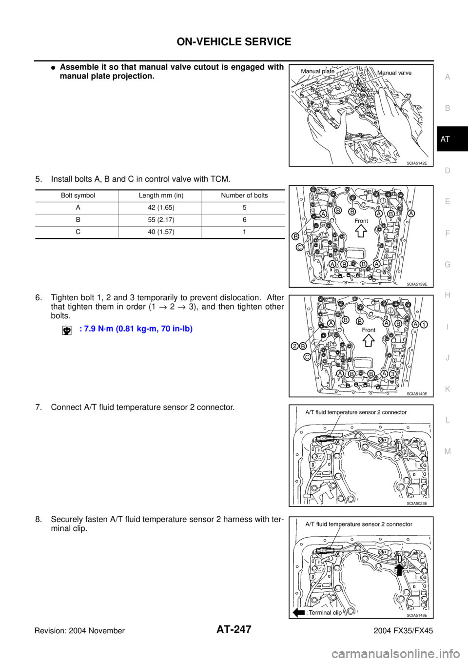
�Assemble it so that manual valve cutout is engaged with
manual plate projection.
5. Install bolts A, B and C in control valve with TCM.
6. Tighten bolt 1, 2 and 3 temporarily to prevent dislocation. After
that tighten them in order (1 → 2 → 3), and then tighten other
bolts.
7. Connect A/T fluid temperature sensor 2 connector.
8. Securely fasten A/T fluid temperature sensor 2 harness with ter-
minal clip.
SCIA5142E
Bolt symbol Length mm (in) Number of bolts
A 42 (1.65) 5
B 55 (2.17) 6
C 40 (1.57) 1
SCIA5139E
: 7.9 N·m (0.81 kg-m, 70 in-lb)
SCIA5140E
SCIA5023E
SCIA5146E
Page 328 of 4449
ON-VEHICLE SERVICE
AT-251
D
E
F
G
H
I
J
K
L
MA
B
AT
Revision: 2004 November 2004 FX35/FX45
Installation
CAUTION:
After completing installation, check A/T fluid leakage and fluid level. Refer to AT- 1 2 , "
Changing A/T
Fluid" , AT- 1 2 , "Checking A/T Fluid" .
1. Install A/T fluid temperature sensor 2 to bracket.
2. Install A/T fluid temperature sensor 2 in control valve with TCM.
(With bracket.)
3. Connect A/T fluid temperature sensor 2 connector.
4. Securely fasten A/T fluid temperature sensor 2 harness with ter-
minal clip.
5. Install oil pan to transmission case.
a. Install oil pan gasket to oil pan.
CAUTION:
�Do not reuse oil pan gasket.
�Install it in the direction to align hole positions.
�Complete remove all moisture, oil and old gasket, etc. from oil pan mounting surface.
SCIA5264E
: 7.9 N·m (0.81 kg-m, 70 in-lb)
SCIA5302E
SCIA5023E
SCIA5146E
Page 337 of 4449
ACS007H2
COMPONENTS
REMOVAL
1. Disconnect the battery cable from the negative terminal.
2")
AT-260
ON-VEHICLE SERVICE
Revision: 2004 November 2004 FX35/FX45
Revolution Sensor Components (2WD Models Only)ACS007H2
COMPONENTS
REMOVAL
1. Disconnect the battery cable from the negative terminal.
2. Drain ATF through drain plug.
3. Remove front cross bar. Refer to FSU-8, "
Components" .
4. Remove exhaust front tube and center muffler with power tool. Refer to EX-3, "
Removal and Installation" .
5. Remove rear propeller shaft. Refer to PR-7, "
Removal and Installation" .
6. Remove oil pan and oil pan gasket.
7. Support transmission assembly with a transmission jack.
CAUTION:
When setting transmission jack, place wooden blocks to
prevent from damaging control valve with TCM and trans-
mission case.
8. Remove engine rear member with power tool. Refer to AT- 2 6 6 ,
"Removal and Installation (2WD Models)" .
1. Rear extension 2. Transmission 3. Revolution sensor
4. Oil pan gasket 5. Oil pan 6. Oil pan mounting bolt
7. Drain plug gasket 8. Drain plug 9. Self-sealing bolt
SCIA5145E
SCIA2308E
Page 343 of 4449
ACS002S1
COMPONENTS
REMOVAL
CAUTION:
When removing the A/T assem")
AT-266
TRANSMISSION ASSEMBLY
Revision: 2004 November 2004 FX35/FX45
TRANSMISSION ASSEMBLYPFP:31020
Removal and Installation (2WD Models)ACS002S1
COMPONENTS
REMOVAL
CAUTION:
When removing the A/T assembly from engine, first remove the crankshaft position sensor (POS) from
the A/T assembly.
Be careful not to damage sensor edge.
1. Disconnect the battery cable from the negative terminal.
2. Remove engine cover.
3. Remove A/T fluid level gauge.
4. Remove engine under cover with power tool.
5. Remove front cross bar. Refer to FSU-8, "
Components" .
6. Remove exhaust front tube and center muffler with power tool. Refer to EX-3, "
Removal and Installation" .
7. Remove three way catalyst. Refer to EM-26, "
Removal and Installation" .
8. Remove rear propeller shaft. Refer to PR-7, "
Removal and Installation" .
9. Remove control rod. Refer to AT- 2 3 3 , "
Control Device Removal and Installation" .
1. Transmission assembly 2. A/T fluid charging pipe 3. O-ring
4. Fluid cooler tube 5. Copper washer 6. A/T fluid level gauge
7. Engine rear member 8. Insulator
SCIA5050E
Page 347 of 4449

REMOVAL
CAUTION:
When removing the A/T assembly from engine, first remove the crankshaft position sensor (PO")
AT-270
TRANSMISSION ASSEMBLY
Revision: 2004 November 2004 FX35/FX45
COMPONENTS (FOR VK45DE)
REMOVAL
CAUTION:
When removing the A/T assembly from engine, first remove the crankshaft position sensor (POS) from
the A/T assembly.
Be careful not to damage sensor edge.
1. Disconnect the battery cable from the negative terminal.
2. Remove engine cover.
3. Remove A/T fluid level gauge.
4. Remove engine under cover with power tool.
5. Remove front cross bar. Refer to FSU-8, "
Components" .
6. Remove exhaust front tube and center muffler with power tool. Refer to EX-3, "
Removal and Installation" .
7. Remove three way catalyst. Refer to EM-26, "
Removal and Installation" (for VQ35DE models), EM-178,
"Removal and Installation" (for VK45DE models).
8. Remove front propeller shaft. Refer to PR-4, "
Removal and Installation" .
9. Remove rear propeller shaft. Refer to PR-7, "
Removal and Installation" .
10. Remove control rod. Refer to AT- 2 3 3 , "
Control Device Removal and Installation" .
1. A/T fluid charging pipe 2. O-ring 3. Insulator
4. Engine rear member 5. Heat insulator 6. Copper washer
7. Fluid cooler tube 8. Transmission assembly 9. A/T fluid level gauge
SCIA5194E